
B M Sharma Solutions for Chapter: Electrical Measuring Instruments, Exercise 2: Concept application Excercise
B M Sharma Physics Solutions for Exercise - B M Sharma Solutions for Chapter: Electrical Measuring Instruments, Exercise 2: Concept application Excercise
Attempt the free practice questions on Chapter 6: Electrical Measuring Instruments, Exercise 2: Concept application Excercise with hints and solutions to strengthen your understanding. PHYSICS for Joint Entrance Examination JEE (Advanced) Electrostatics and Current Electricity solutions are prepared by Experienced Embibe Experts.
Questions from B M Sharma Solutions for Chapter: Electrical Measuring Instruments, Exercise 2: Concept application Excercise with Hints & Solutions
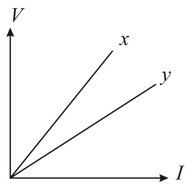
The variation of potential difference with length in case of two potentiometers and is as shown in the figure. Which of these two will you prefer for comparing the emfs of the two cells and why?
Two unknown resistances and are placed on the left and right gaps of a meter bridge. The null point in the galvanometer is obtained at a distance of from left. A resistance of is now connected in parallel across . The null point is then found by shifting the sliding contact towards left by . Calculate and .
In an experiment with a potentiometer, the null point is obtained at a distance of along the wire from the common terminal with a Leclanche cell. When a shunt resistance of is connected across the cell, the null point shifts to a distance of from the common terminal. What is the internal resistance of the cell?
In the experiment of calibration of voltmeter, a standard cell of emf is balanced against of potentiometer wire. The potential difference across the ends of a resistance is found to balance against of the wire. The corresponding reading of the voltmeter is . Find the error in the reading of voltmeter.
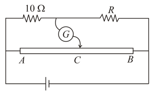
The resistance wire in the balancing setup shown in the figure is long. When , no deflection occurs in the galvanometer. Find the unknown resistance .
The figure shows a potentiometer arrangement with and rheostat of variable resistance . For null deflection point is found at from . For the unknown value of null deflection point was at from , then the value of .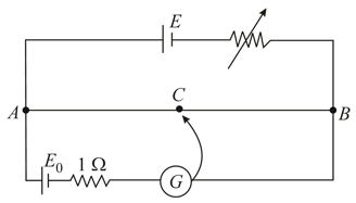
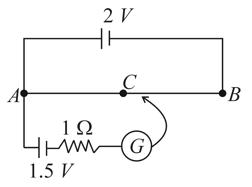
A battery of negligible internal resistance is connected across a uniform wire of length . The positive terminal of another battery of emf and internal resistance is joined to the point as shown in figure. Take the potential at to be zero.
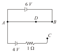
(a) What are the potentials at the points and ?
(b) At which point and of the wire the potential is equal to the potential at ?
(c) If the points and are connected by a wire, what will be the current through it?
(d) If the battery is replaced by battery, what would be the answers of parts (a) and (b)?
A battery of emf and negligible internal resistance is connected across a uniform wire of length and resistance . The appropriate terminals of a cell of emf and internal resistance is connected to one end of the wire and the other terminal of the cell is connected through a sensitive galvanometer to a slider on the wire. What is the length of the wire that will be required to produce zero deflection of the galvanometer? How will the balancing length change?
(a) When a coil of resistance is placed in series with the accumulator.
(b) The cell of is shunted with resistor?


