
David Sang and Graham Jones Solutions for Chapter: Motion of Charged Particles, Exercise 9: EXAM-STYLE QUESTIONS
David Sang Physics Solutions for Exercise - David Sang and Graham Jones Solutions for Chapter: Motion of Charged Particles, Exercise 9: EXAM-STYLE QUESTIONS
Attempt the free practice questions on Chapter 25: Motion of Charged Particles, Exercise 9: EXAM-STYLE QUESTIONS with hints and solutions to strengthen your understanding. Physics for Cambridge International AS & A Level Coursebook 3rd Edition Digital Access solutions are prepared by Experienced Embibe Experts.
Questions from David Sang and Graham Jones Solutions for Chapter: Motion of Charged Particles, Exercise 9: EXAM-STYLE QUESTIONS with Hints & Solutions
This diagram shows an electron tube. Electrons emitted from the cathode accelerate towards the anode and then Explain why the beam curves upwards between the plates pass into a uniform electric field created by two oppositely charged horizontal metal plates.
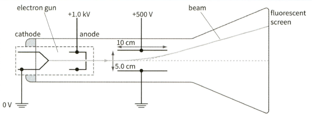
Explain how the pattern formed on the fluorescent screen shows that all the electrons have the same speed as they leave the anode.
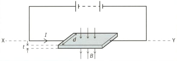
This diagram shows a thin slice of metal of thickness and width . The metal slice is in a magnetic field of flux density and carries a current , as shown.

Derive an expression for the Hall voltage in terms of the number density of the charge carriers in the metal and the charge on an electric iron.
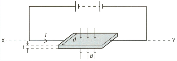
This diagram shows a thin slice of metal of thickness and width . The metal slice is in a magnetic field of flux density and carries a current , as shown.
Given that theme an drift velocity v of the free electrons in the metal.
This diagram shows a thin slice of metal of thickness and width . The metal slice is in a magnetic field of flux density and carries a current , as shown.

Given that the Hall voltage across the metal slice.
This diagram shows a thin slice of metal of thickness and width . The metal slice is in a magnetic field of flux density and carries a current , as shown.

(c) Given that
Calculate the percentage uncertainty in the mean drift velocity v of the electrons, assuming the percentage uncertainties in the quantities are as shown.
This diagram shows a thin slice of metal of thickness and width . The metal slice is in a magnetic field of flux density and carries a current , as shown.
Explain why, in terms of the movement of electrons, the Hall voltage increases when I increase.
This diagram shows a thin slice of metal of thickness and width . The metal slice is in a magnetic field of flux density and carries a current , as shown.

Explain why, in terms of the movement of electrons, the Hall voltage increases when increase.
This diagram shows a thin slice of metal of thickness and width . The metal slice is in a magnetic field of flux density and carries a current , as shown.

Explain why, when the slice of metal is rotated about the horizontal axis the Hall voltage varies between a maximum positive value and a maximum negative value.


