Ammeter and Voltmeter and Their Connection in Circuit
Ammeter and Voltmeter and Their Connection in Circuit: Overview
This topic shows the diagram of the connections of ammeter and voltmeters. An ammeter is an electrical device used to measure the electric current. A voltmeter is used to measure the potential difference between two points in an electric circuit.
Important Questions on Ammeter and Voltmeter and Their Connection in Circuit
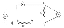
Identify the circuit in which the electrical components have been properly connected:
A student set up electric circuit shown here for finding the equivalent resistance to two resistors in series. In this circuit.
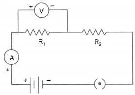
The circuit diagram shown below is used to find the effective resistance of two resistors in series. Which circuit diagram represents correctly?
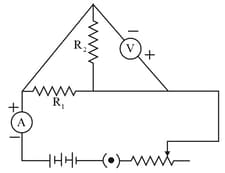
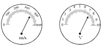
The number of divisions in ammeter of range is and voltmeter of range is . When the switch of the circuit given below is closed, ammeter reading is at division and voltmeter reading is at division. The value of resistance of the resistor is
An ammeter and a voltmeter are joined in series to a cell. Their readings are and respectively. If a resistor is now joined in parallel with the voltmeter
To calculate the equivalent resistance when and are connected in parallel, a student is not able to perform the experiment for the given circuit diagram:
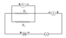
The correct reason is:
A student sets up his circuit for finding the equivalent resistance of a series combination of two given resistors and in the manner as shown below. He did not obtain the correct result in his experiment because of a mistake in the circuit. This mistake can be corrected by shifting the component:
A battery (of internal resistance ) is connected across a resistor and a switch in series, as shown:
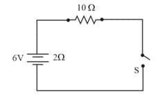
If the switch is kept in the off position, as shown in the figure, then:
To determine the equivalent resistance of two resistors, when connected in series, the correct way of connecting the ammeter and voltmeter in the circuit is:
To study the dependence of current on the potential difference across a resistor, two students used the two setups shown in figs. and respectively. They kept the contact in different positions marked (1), (2), (3), (4) in the two figures.
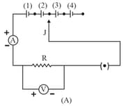
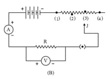
For the two students, their ammeter and voltmeter readings will be minimum when the contact is in the position:
The only correct statement for the following circuit is:
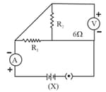
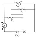
The only correct statement for the two circuits X and Y shown below:
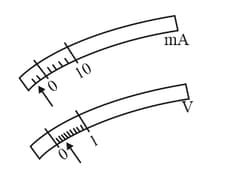
The rest positions of the needles in a milliammeter and voltmeter when not being used in a circuit are shown in the figure. The 'zero error' and 'least count' of these two instruments are
In an experiment to determine the equivalent resistance of two resistors and in series, which one of the following is the correct ways of connecting the voltmeter in the circuit?
The following instruments are available in a laboratory.
Milliammeter of range and least count .
Milliammeter of range and least count .
Voltmeter of range and least count .
Voltmeter of range and least count .
Out of the following pairs of instruments which pair would be the best choice for carrying out the experiment to determine the equivalent resistance of two resistors connected in series.
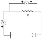
The current flowing through a conductor and the potential difference across its two ends are as per readings of the ammeter and voltmeter shown below. The resistance of the conductor would be
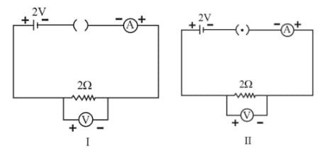
For the circuits shown in figures and the voltmeter reading would be
In a voltmeter, there are division between the mark and mark. The least count of the voltmeter is
The following circuit diagrams shows the experimental set-up for the study of dependence of current on potential difference. Which two circuit components are connected in series?
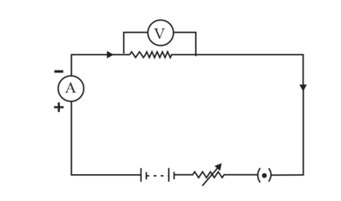
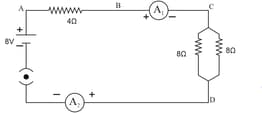
Find out the following in the electric circuit given in the figure.
The difference in ammeter readings, if any.