Embibe Experts Solutions for Chapter: Alternating Current, Exercise 3: Exercise-3
Embibe Experts Physics Solutions for Exercise - Embibe Experts Solutions for Chapter: Alternating Current, Exercise 3: Exercise-3
Attempt the practice questions on Chapter 28: Alternating Current, Exercise 3: Exercise-3 with hints and solutions to strengthen your understanding. Alpha Question Bank for Medical: Physics solutions are prepared by Experienced Embibe Experts.
Questions from Embibe Experts Solutions for Chapter: Alternating Current, Exercise 3: Exercise-3 with Hints & Solutions
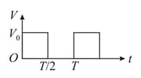
The value of potential difference shown in the figure is:
Which of the following combinations should be selected for better tuning of an circuit used for communication
The potential differences across the resistance, capacitance and inductance are and , respectively in an circuit. The power factor of this circuit is,
An inductor , a capacitor and a resistor are connected in series across a source of emf, . The power loss in the circuit is:
In a series circuit and the voltage and frequency of the main supply is and respectively. On taking out the capacitance from the circuit the current lags behind the voltage by On taking out the inductor from the circuit the current leads the voltage by The power dissipated in the circuit is
In an A.C. circuit, the instantaneous and current are given by , . In one cycle of A.C., the average power consumed by the circuit and the wattless current are, respectively:
A power transmission line feeds input power at to a step down transformer with its primary windings having turns. The output power is delivered at by the transformer. If the current in the primary of the transformer is and its efficiency is the output current would be
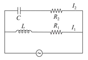
In the above circuit and Current in path is and in path it is . The voltage of A.C. source is given by , the phase difference between and is :