
Embibe Experts Solutions for Chapter: Alternating Current, Exercise 1: Exercise-1
Embibe Experts Physics Solutions for Exercise - Embibe Experts Solutions for Chapter: Alternating Current, Exercise 1: Exercise-1
Attempt the free practice questions on Chapter 28: Alternating Current, Exercise 1: Exercise-1 with hints and solutions to strengthen your understanding. Beta Question Bank for Engineering: Physics solutions are prepared by Experienced Embibe Experts.
Questions from Embibe Experts Solutions for Chapter: Alternating Current, Exercise 1: Exercise-1 with Hints & Solutions
In circuit, the voltage across the terminals of a resistance and current will be
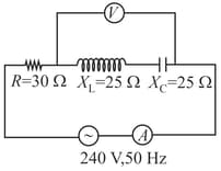
In the circuit shown in the figure, neglecting source resistance, the voltmeter and ammeter readings will respectively be
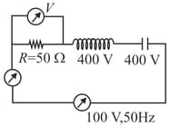
In the circuit, shown in the figure, the source gives a voltage volt neglecting source resistance, the voltmeter and ammeter reading will be
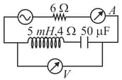
A coil has an inductance of henry and is joined in series with a resistance of . When the alternating emf of at is applied to it then the phase through which current lags behind the applied emf and the wattless component of maximum current in the circuit will bee respectively
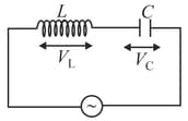
The current , potential difference across the inductor and potential difference across the capacitor in circuit as shown in the figure are best represented vectorially as
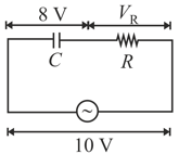
In a series circuit shown in figure, the applied voltage is and voltage across capacitor is found to be , then the voltage across , and the phase difference between current and the applied voltage will respectively be
In series circuit and is resistance. Now a capacitor with is added in series. Ration of new to old power factor is
The voltage-time graph for the triangle wave has a peak value. is as shown in the figure:
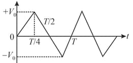
The value of in time interval from to is


