NCERT Solutions for Chapter: Semiconductor Electronics: Materials, Devices and Simple Circuits, Exercise 4: LA
NCERT Physics Solutions for Exercise - NCERT Solutions for Chapter: Semiconductor Electronics: Materials, Devices and Simple Circuits, Exercise 4: LA
Attempt the practice questions on Chapter 14: Semiconductor Electronics: Materials, Devices and Simple Circuits, Exercise 4: LA with hints and solutions to strengthen your understanding. NCERT Exemplar Physics - Class 12 solutions are prepared by Experienced Embibe Experts.
Questions from NCERT Solutions for Chapter: Semiconductor Electronics: Materials, Devices and Simple Circuits, Exercise 4: LA with Hints & Solutions
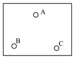
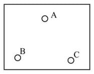
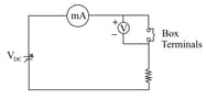
Consider a box with three terminals on top of it as shown in figure

Three components namely, two germanium diodes and one resistor are connected across these three terminals in some arrangement. A student performs an experiment in which any two of these three terminals are connected in the circuit shown.

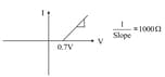
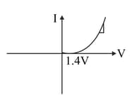
The student obtains graphs of current-voltage characteristics for unknown combination of components between the two terminals connected in the circuit.
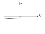
The graphs when is positive and is negative is

From this graph of current – voltage characteristic shown in Fig. determine the arrangement of components between and .
Consider a box with three terminals on top of it as shown in figure
Three components namely, two germanium diodes and one resistor are connected across these three terminals in some arrangement.
A student performs an experiment in which any two of these three terminals are connected in the circuit shown.

The student obtains graphs of current-voltage characteristics for unknown combination of components between the two terminals connected in the circuit.
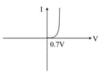
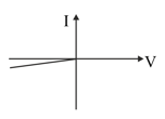
The graphs when is negative and is positive is
From these graphs of current – voltage characteristic shown in figure, determine the arrangement of components between and .
Consider a box with three terminals on top of it as shown in figure

Three components namely, two germanium diodes and one resistor are connected across these three terminals in some arrangement. A student performs an experiment in which any two of these three terminals are connected in the circuit shown.

The student obtains graphs of current-voltage characteristics for unknown combination of components between the two terminals connected in the circuit.
The graphs when is negative and is positive
From these graphs of current – voltage characteristic shown determine the arrangement of components between and .
Consider a box with three terminals on top of it as shown in figure
Three components namely, two germanium diodes and one resistor are connected across these three terminals in some arrangement. A student performs an experiment in which any two of these three terminals are connected in the circuit shown

The student obtains graphs of current-voltage characteristics for unknown combination of components between the two terminals connected in the circuit.
The graphs when is positive and is negative
From these graphs of current – voltage characteristic shown in figure determine the arrangement of components between and .
Consider a box with three terminals on top of it as shown in figure

Three components namely, two germanium diodes and one resistor are connected across these three terminals in some arrangement.
A student performs an experiment in which any two of these three terminals are connected in the circuit shown.
The student obtains graphs of current-voltage characteristics for unknown combination of components between the two terminals connected in the circuit.
The graphs when is positive and is negative
From these graphs of current – voltage characteristic shown in Fig. determine the arrangement of components between and .
Consider a box with three terminals on top of it as shown in figure

Three components namely, two germanium diodes and one resistor are connected across these three terminals in some arrangement.
A student performs an experiment in which any two of these three terminals are connected in the circuit shown.

The student obtains graphs of current-voltage characteristics for unknown combination of components between the two terminals connected in the circuit.
The graphs when is negative and is positive
From these graphs of current – voltage characteristic shown in Fig. determine the arrangement of components between and .
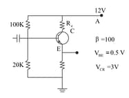
For the transistor circuit shown in figure, evaluate given and
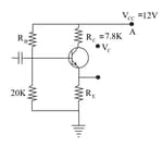
In the circuit shown in figure, find the value of .