Charging and Discharging of a Capacitor Through a Resistance
Important Questions on Charging and Discharging of a Capacitor Through a Resistance
The space between the plates of a parallel plate capacitor is completely filled with a material of resistivity and dielectric constant . The capacity of the capacitor with the given dielectric medium between the plates is . Find the leakage current if a potential difference is applied across the capacitor.
A parallel plate capacitor of capacitance is connected to a cell of emf and is fully charged. Now a dielectric slab of thickness equal to the gap between the plates is completely filled in the gap, keeping the cell connected. During the filling process,
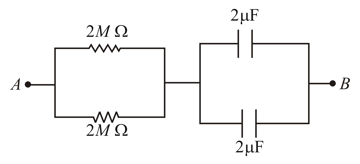
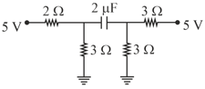
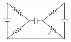
At time a battery of is connected across points and in the given circuit. If the capacitors have no charge initially, at what time (in ) does the voltage across them becomes ? [Take ]
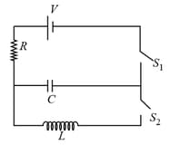
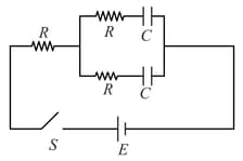
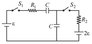
In an circuit, as shown below, both switches are open initially. Now the switch is closed and kept open. ( is the charge on the capacitor and is the capacitive time constant). Which of the following statement is correct?
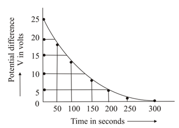
The figure shows an experimental plot discharging of a capacitor in an circuit. The time constant of this circuit lies between:
A resistor and capacitor in series are connected through a switch to direct supply. Across the capacitor is a neon bulb that lights up at . Calculate the value of to make the bulb light up after the switch has been closed.
Let be the capacitance of a capacitor discharging through a resistor . Suppose be the time taken for the energy stored in the capacitor to reduce to half its initial value and be the time taken for the charge to reduce to one-fourth of its initial value. Then the ratio will be,
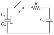
In the circuit shown, the capacitor is initially charged with charge . The switch is closed at time . The charge on after time is
The charge on the capacitor in steady-state in the circuit shown (figure) is
The switch in the circuit diagram (figure) is closed at . The charge on capacitors at any time is,
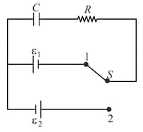
Initially, switch is connected to position for a long time (figure). The net amount of heat generated in the circuit after it is shifted to position is
Each resistor in the following circuit (figure) has a resistance of and the capacitors have a capacitance of . The battery voltage is . The voltage across the resistor in the following circuit in steady state is,
In the circuit shown (figure), the switch is closed first and is kept closed for a long time. Now, is closed, Just after that instant, the current thought is,
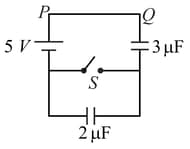
In the figure, the charge that flows from to when the switch is closed is,