
Ammeter
Important Questions on Ammeter
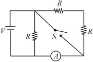
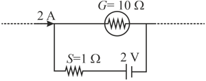
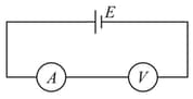
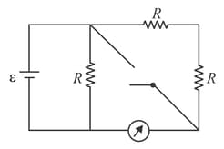
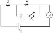
In the circuit shown, and . With the switch open the reading of the ammeter is one-third its reading when is closed. Calculate the resistance of the ammeter (in ).
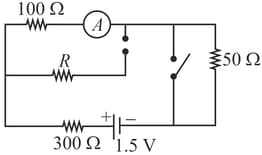
In the circuit shown in the figure the reading of an ideal ammeter is the same with both switches open as with both closed then find the resistance (in ).
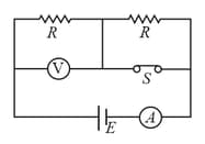
In the circuit shown, battery, ammeter and voltmeter are ideal and the switch is initially closed as shown. When switch is opened,
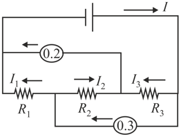
A circuit contains an ideal battery, three resistors and two ideal ammeters. The ammeters read and . After two of the resistors are switched, the readings of the ammeters did not change. Find the battery current.
The galvanometer shown in the figure has resistance It is shunted by a series combination of a resistance and an ideal cell of emf A current passes as shown:
Three ammeters and of resistances and respectively, are joined as shown in the figure.
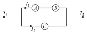
When some potential difference is applied across the terminals and their readings are and respectively, then
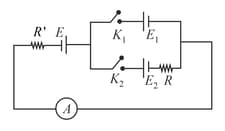
Two ideal batteries and two ammeters are arranged as shown in the figure.
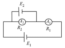
In the above figure, if the polarity of is reversed, then
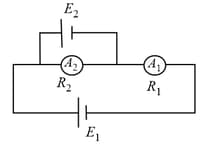
Two ideal batteries and two ammeters are arranged as shown in the figure.
A non-ideal ammeter and voltmeter are connected in series with an ideal cell of emf as shown in the figure. Reading of the voltmeter is When resistance is added in parallel to the voltmeter, its reading becomes and the reading of the ammeter becomes times the earlier value. Find the value of (in ).
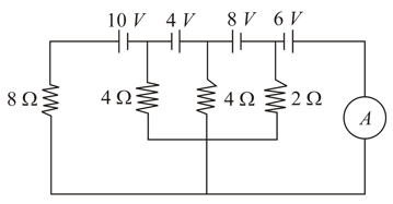
Find the reading of the ideal ammeter connected in the given circuit. Assume that the cells have negligible internal resistance.
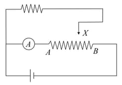
In circuit shown in figure, terminal is brought from point to . Then reading of ammeter
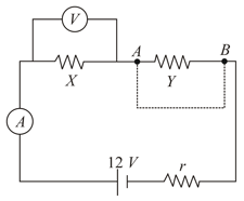
When an ammeter of negligible internal resistance is inserted in series with circuit it reads . When the voltmeter of very large resistance is connected across it reads . When the point and are shorted by a conducting wire, the voltmeter measures . The internal resistance of the battery is equal to
In the circuit shown, the reading of the ammeter is doubled after the switch is closed. Each resistor has the resistance and the ideal cell has an emf of . Then, the ammeter
In the given arrangement, the reading of ammeter is same in each case when either or is closed. The reading of the ammeter is,
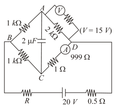
Calculate the energy stored in the capacitor of capacitance . The voltmeter gives a reading of and the ammeter reads .
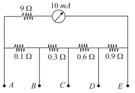
A milli-ammeter of range and resistance are joined in a circuit as shown in the figure. The meter gives full-scale deflection, when the current in the main circuit is , and are used as terminals. The value of is
In the given circuit (figure), when key is open, the reading of the ammeter is . Now the key is closed, then the correct statement is-
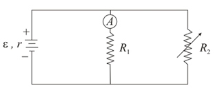
In the given circuit (figure) in which case will the ammeter reading not change when is varied?
When a galvanometer is shunted with a resistance, the deflection is reduced to . If the galvanometer is further shunted with a wire, the new deflection will be (assuming the main current remains the same),
An ammeter is obtained by shunting a galvanometer with a resistance. What additional shunt should be connected across it to double the range?


