
David Sang and Graham Jones Solutions for Chapter: Alternating Currents, Exercise 10: EXAM-STYLE QUESTIONS
David Sang Physics Solutions for Exercise - David Sang and Graham Jones Solutions for Chapter: Alternating Currents, Exercise 10: EXAM-STYLE QUESTIONS
Attempt the free practice questions on Chapter 27: Alternating Currents, Exercise 10: EXAM-STYLE QUESTIONS with hints and solutions to strengthen your understanding. Physics for Cambridge International AS & A Level Coursebook 3rd Edition Digital Access solutions are prepared by Experienced Embibe Experts.
Questions from David Sang and Graham Jones Solutions for Chapter: Alternating Currents, Exercise 10: EXAM-STYLE QUESTIONS with Hints & Solutions
Explain what is meant by root-mean-square voltage.
Electrical energy is supplied by a high-voltage power line that has a total resistance of . At the input to the line, the root-mean-square (r.m.s.) voltage has a value of 400 kV and the input power is 500 MW. Calculate the minimum voltage that the insulators that support the line must withstand without breakdown.
Electrical energy is supplied by a high-voltage power line that has a total resistance of . At the input to the line, the root-mean-square (r.m.s.) voltage has a value of 400 kV and the input power is 500 MW.
(b) (i) Calculate the value of the r.m.s. current in the power line.
Electrical energy is supplied by a high-voltage power line that has a total resistance of . At the input to the line, the root-mean-square (r.m.s.) voltage has a value of 400 kV and the input power is 500 MW.
(b) (ii) Calculate the power loss on the line.
Electrical energy is supplied by a high-voltage power line that has a total resistance of . At the input to the line, the root-mean-square (r.m.s.) voltage has a value of 400 kV and the input power is 500 MW. Suggest why it is an advantage to transmit the power at a high voltage.
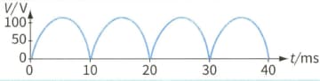
A student has designed a full-wave rectifier circuit. The output voltage for this circuit is taken across a resistor of resistance . The variation of the output voltage with time is shown.

A capacitor is now connected across the resistor. The graph shows the new variation of the output voltage with time.

Explain the variation of the output variation between points AB.
A student has designed a full-wave rectifier circuit. The output voltage for this circuit is taken across a resistor of resistance . The variation of the output voltage with time is shown.

A capacitor is now connected across the resistor. The graph shows the new variation of the output voltage with time.

Explain the variation of the output variation between points BC.
A student has designed a full-wave rectifier circuit. The output voltage for this circuit is taken across a resistor of resistance . The variation of the output voltage with time is shown.
A capacitor is now connected across the resistor. The graph shows the new variation of the output voltage with time.
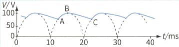
Use the second graph to determine the value of the capacitance C.


