S L Arora Solutions for Chapter: Electromagnetic Induction, Exercise 3: SHORT ANSWER CONCEPTUAL PROBLEMS
S L Arora Physics Solutions for Exercise - S L Arora Solutions for Chapter: Electromagnetic Induction, Exercise 3: SHORT ANSWER CONCEPTUAL PROBLEMS
Attempt the free practice questions on Chapter 6: Electromagnetic Induction, Exercise 3: SHORT ANSWER CONCEPTUAL PROBLEMS with hints and solutions to strengthen your understanding. New Simplified Physics (Vol 1) For Class 12 solutions are prepared by Experienced Embibe Experts.
Questions from S L Arora Solutions for Chapter: Electromagnetic Induction, Exercise 3: SHORT ANSWER CONCEPTUAL PROBLEMS with Hints & Solutions
Figure 6.72 given below shows an arrangement by which current flows through the bulb (X) connected with coil , when a.c. is passed through coil .
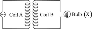
Explain the following observation:
If a copper sheet is inserted in the gap between the coils how the brightness of the bulb would change?
A coil is connected to a voltmeter and the other coil to an alternating current source . If a large copper sheet , is placed between the two coils, how does the induced emf in the coil change due to current in the coil ?
A coil is connected to low voltage bulb and placed near another coil as shown in Fig. 6.74. Give reasons to explain the following observation:

The bulb '' lights.
A coil is connected to low voltage bulb and placed near another coil as shown in Fig. 6.74. Give reasons to explain the following observation:
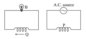
Bulb gets dimmer if the coil is moved towards left.
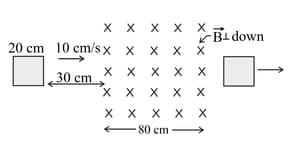
A square loop of side is placed horizontally in a uniform magnetic field acting vertically downwards as shown in the Fig. 6.75. The loop is pulled with a constant velocity of till it goes out of the field.
(i) Depict the direction of the induced current in the loop as it goes out of the field. For how long would the current in the loop persist?
(ii) Plot a graph showing the variation of magnetic flux and induced emf as a function of time.
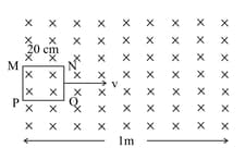
A square loop of side is initially kept away from a region of uniform magnetic field of as shown in Fig. 6.77. It is then moved towards the right with a velocity of till it goes out of the field. Plot a graph showing the variation of magnetic flux () through the loop with time ().
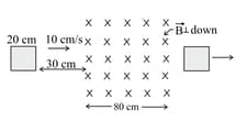
A square loop of side is initially kept away from a region of uniform magnetic field of as shown in Fig. 6.77. It is then moved towards the right with a velocity of till it goes out of the field. Plot a graph showing the variation of induced emf () in the loop with time .

A square loop of side is initially kept away from a region of uniform magnetic field of as shown in Fig. 6.77. It is then moved towards the right with a velocity of till it goes out of the field. Plot a graph showing the variation of induced current in the loop if it has resistance of .