S. L. Arora Solutions for Chapter: Semiconductor Devices and Digital Circuits, Exercise 4: Problems For Practice
S. L. Arora Physics Solutions for Exercise - S. L. Arora Solutions for Chapter: Semiconductor Devices and Digital Circuits, Exercise 4: Problems For Practice
Attempt the free practice questions on Chapter 6: Semiconductor Devices and Digital Circuits, Exercise 4: Problems For Practice with hints and solutions to strengthen your understanding. PHYSICS A Reference Book for Class 12 Volume 2 solutions are prepared by Experienced Embibe Experts.
Questions from S. L. Arora Solutions for Chapter: Semiconductor Devices and Digital Circuits, Exercise 4: Problems For Practice with Hints & Solutions
The power gain for amplifier is and the voltage amplification factor is Find the collector current when the base current is .
The current gain of a transistor in CB configuration is Find the change in collector current corresponding to a change of in the emitter current. What would be the change in base current?
In common‐emitter transistor amplifier, the load resistance of the output circuit is times the load resistance of the input circuit. If , then calculate the voltage gain.
In common‐emitter transistor amplifier, an increase of in the base current causes an increase of in the collector current. Calculate gain . What will be the change in emitter current? Also calculate current gain
The base current of a transistor is and collector current is (i) Determine the value of and A change of in the base current produces a change of in the collector current. Find .
A transistor is used in common emitter mode in an amplifier circuit. When a signal of is added to the base‐emitter voltage, the base current changes by and collector current by The load resistance is . Calculate (i) the current gain (ii) the input resistance (iii) transconductance and (iv) voltage gain.
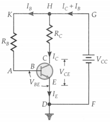
In the circuit shown in figure, the base current , base resistor , collector resistor , the collector current and the . voltage in the collector circuit . (i) Can this circuit be used as an amplifier? (ii) What happens if the resistance is and and remains same as above?
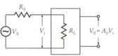
As shown in figure, an amplifier of no-load gain and input resistance is connected to external signal via a series resistance of . What is the apparent voltage gain?