
Circuit Diagram
Important Questions on Circuit Diagram
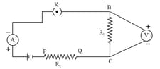
The picture shows an electric circuit.
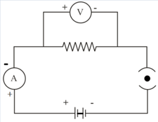
Which of these is true about the circuit?
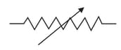
What does the symbol mean in an electric circuit?
Observe the circuit shown below. All the three switches are open.
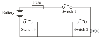
Identify the switch/switches that on being closed will cause the fuse to blow.
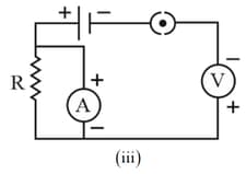
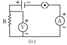
Suresh arranges the electric circuit shown below to measure the current flowing through and the potential difference of a bulb.
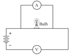
Is the circuit correct? If not, then identify the mistake.
A student sets up his circuit for finding the equivalent resistance of a series combination of two given resistors and in the manner as shown below. He did not obtain the correct result in his experiment because of a mistake in the circuit. This mistake can be corrected by shifting the component:
Why is an ammeter likely to burn out if you connect it in parallel?
The rest positions of the needles in a milliammeter and voltmeter not in use are as shown in Fig A. When a student uses these in his experiment, the reading of the needles are in the positions shown in Fig B.
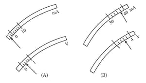
The corrected values of current and voltage in the experiment are
An ammeter has divisions between and marks on the scale. The least count of this ammeter is :
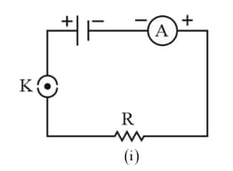
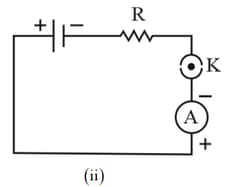
The following four circuits have been made for studying the dependence of current on the potential difference across a resistor.
The correct circuit is:
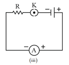
Identify the circuit (figure) in which the electrical components have been properly connected.
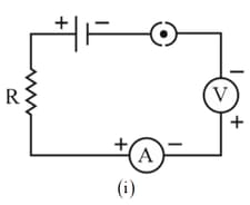
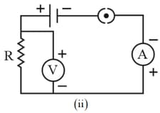
A cell, a resistor, a key and ammeter are arranged as shown in the circuit diagrams of the figure. The current recorded in the ammeter will be:
An electric bulb of resistance and a resistance wire of are connected in series with a battery.
Draw the circuit diagram and calculate:
(a) the total resistance of the circuit.
(b) current through the circuit.
(c) the potential difference across the electric bulb.
(d) the potential difference across the resistance wire.


