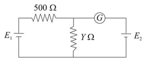
A potentiometer arrangement is shown in the figure. The driver cell has emf and internal resistance .
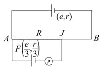
The resistance of potentiometer wire is . is the cell of emf and internal resistance . Balance point () can be obtained for all finite values of
The resistance of potentiometer wire is . is the cell of emf and internal resistance . Balance point () can be obtained for all finite values of
Important Questions on Electrical Measuring Instruments
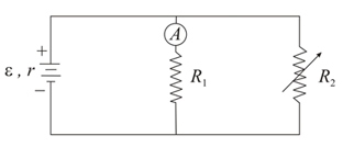
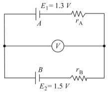
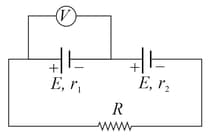
Two cells and of electromotive forces and , respectively, are arranged as shown in the figure. The voltmeter (assumed ideal) reads , the internal resistances of cells and are and , respectively. Which of the following is correct?
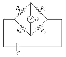
The Wheatstone's bridge shown in the figure is balanced. If the positions of the cell and the galvanometer are now interchanged, will show zero deflection-
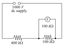
A constant voltage dc source is connected, as shown in the figure, across two resistors of resistances and . What is the reading of the voltmeter, also of resistance , when connected across the second resistor as shown?