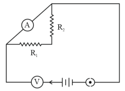
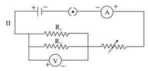
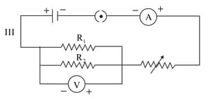
A student sets up her circuit, for finding the equivalent resistance of two resistors and in series, in the manner as shown. She did not obtain the correct result in her experiment because of a mistake in her circuit. What mistake did she commit and what should do to correct this mistake?
Important Questions on Electricity
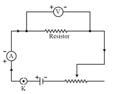
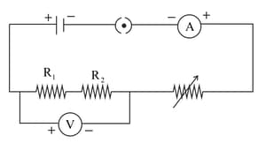
The given circuit diagram shows the experimental arrangement of different circuit components for determination of equivalent resistance of two resistors connected in series. Name the components and shown in the circuit.
For carrying out the experiment, on finding the equivalent resistance of two resistors connected in series, a student sets up the circuit as shown. On further verification, he finds out that the circuit has one or more faults. Mention the fault.
(i) The resistors and have not been correctly connected in series.
(iI) The voltmeter has not been correctly connected in the circuit.
(iii) The ammeter has not been correctly connected in the circuit.
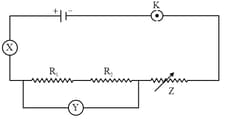
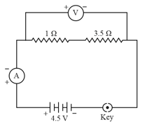
What will be the ammeter reading for the circuit shown in the figure?
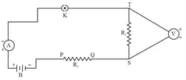
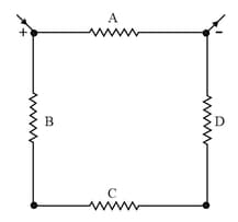
The diagram shows a network of four resistors which is connected to an electric source. Identify the resistors which are connected in series in this network.
The following instruments are available in a laboratory:
Milliammeter of range and least count .
Milliammeter of range and least count .
Voltmeter of range and least count .
Voltmeter of range and least count .
Out of the following pairs of instruments, which pair would be the best choice for carrying out the experiment to determine the equivalent resistance of two resistors connected in series?
Which is the correct setup for determining the equivalent resistance of two and connected in parallel and why?

Which two circuit components are connected in parallel in the following circuit diagram?