
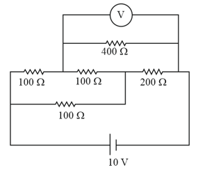
An electrical circuit is shown in the figure. Calculate the potential difference across the resistance of as will be measured by the voltmeter of resistance either by applying Kirchhoff's rules or otherwise.
Important Questions on Current Electricity
A battery of and internal resistance is connected to a resistor of through an ammeter. The resistance of the ammeter is A voltmeter has also been connected to find the potential difference across the resistor.
Draw the circuit diagram.
The ammeter reads What is the resistance of the voltmeter ?
The voltmeter reads what is the zero error in the voltmeter ?
(Hint : zero error observed reading – actual reading)
In the figure the potentiometer wire of length & resistance is joined to the cell of & internal resistance . The cell s e.m.f. is and its internal resistance is The galvanometer will show no deflection then find length
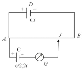
Figure shows a potentiometer used for the determination of internal resistance of The balance point of the cell without in the external circuit is When a resistor of is used in the external circuit of the cell, the balance point shifts to length of the potentiometer wire. Determine the internal resistance of the secondary cell.
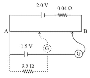
Figure shows a potentiometer with a cell of emf and internal resistance maintaining a potential drop across the potentiometer wireA standard cell which maintains a constant emf of (for very moderate currents up to a few ampere) gives a balance point of length of the wire. To ensure very low currents drawn from the standard cell, a very high resistance of is put in series with it which is shorted close to the balance point. The standard cell is then replaced by a cell of unknown emf E and the balance point found similarly turns out to be at length of the wire.
What is the value of ?
What purpose does the high resistance of have ?
Is the balance point affected by this high resistance?
Is the balance point affected by the internal resistance of the driver cell?
Would the method work in the above situation if the driver cell of the potentiometer had an emf of instead of
Would the circuit work well for determining extremely small emf, say, of the order of few mV (such typical emf of thermocouple)?

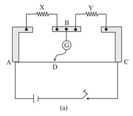
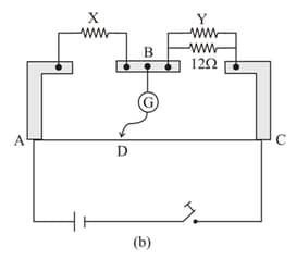
Figure shows a metre bridge (which is nothing but a practical Wheatstone Bridge) consisting of two resistors together in parallel with a metre long constantan wire of uniform cross-section. With the help of a movable contact , one can change the ratio of the resistances of the two segments of the wire until a sensitive galvanometer G connected across shows no deflection. The null point is found to be at a distance of from the end . The resistor is shunted by a resistance of and the null point is found to shift by a distance of Determine the resistance of
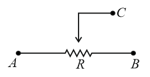
Connect a battery to the terminals and complete the circuit diagram so that it works as a potential divider meter. Indicate the output terminals also.
The drift velocity of electrons in a conducting wire is of the order of , yet the bulb glows very quickly after the switch is put on because


