
An oscilloscope is used to display the variation of voltage across a resistor with time. The trace is shown. The time-base of the oscilloscope is set at and the -gain at .
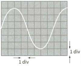
Determine the period and hence the frequency of the alternating voltage.
Important Questions on Alternating Currents
An oscilloscope is used to display the variation of voltage across a resistor with time. The trace is shown. The time-base of the oscilloscope is set at and the -gain at .

Determine the peak voltage and hence the r.m.s. voltage.
An oscilloscope is used to display the variation of voltage across a resistor with time. The trace is shown. The time-base of the oscilloscope is set at and the -gain at .

Determine
(c) the r.m.s. current in the resistor
An oscilloscope is used to display the variation of voltage across a resistor with time. The trace is shown. The time-base of the oscilloscope is set at and the -gain at .
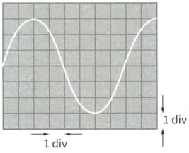
Determine the mean power dissipated in the resistor.
The current in a resistor connected to a steady d.c. supply is . When the same resistor is connected to an a.c. supply, the current in it has a peak value of . The heating effects of the two currents in the resistor are different. Explain why the heating effects are different and state which heating effect is the greater.
The current in a resistor connected to a steady d.c. supply is . When the same resistor is connected to an a.c. supply, the current in it has a peak value of . The heating effects of the two currents in the resistor are different. Calculate the ratio of the power dissipated in the resistor by the d.c. current to the power dissipated in the resistor by the a.c. current.
A sinusoidal voltage of 6.0 V r.m.s. and frequency 50 Hz is connected to a diode and a resistor R of resistance as shown in the diagram.
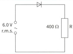
Sketch a graph showing the variation with time of both the supply waveform (use a dotted line) and the voltage across R (use a solid line). Put numerical scales on both the voltage and time axes.
A sinusoidal voltage of 6.0 V r.m.s. and frequency 50 Hz is connected to a diode and a resistor R of resistance as shown in the diagram.

(b) An uncharged capacitor C is connected across R. When the 6.0V r.m.s. supply is switched on, the capacitor charges fully during the first quarter of a cycle. You may assume that the p.d. across the diode is zero when it conducts. For the next three-quarters of the first cycle, the diode stops conducting and the p.d. across R falls to one-half of the peak value. During this time the mean p.d. across R is 5.7V.
For the last three-quarters of the first cycle, calculate the time taken.


