
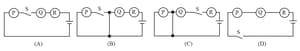
Consider the following circuits:
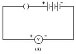
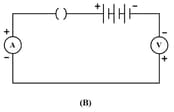
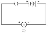
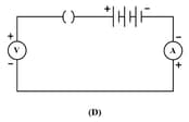
On plugging the key, the voltmeter / ammeter is likely to be damaged:
Important Questions on Multiple Choice Questions
To study the dependence of current on the potential difference across a resistor, two students used the two set ups shown in figs (A) and (B) respectively. They kept the contact J in four different positions, marked (a), (b), (c) and (d) in the two figures.
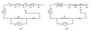
For the two students, their ammeter and Voltmeter readings will be minimum when the contact J is in the position :
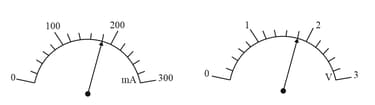
The rest positions of the needles in a milliammeter and voltmeter not in use are as shown in Fig A. When a student uses these in his experiment, the reading of the needles are in the positions shown in Fig B.
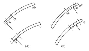
The corrected values of current and voltage in the experiment are
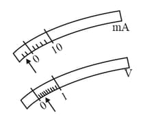
The current flowing through a resistor connected in an electric circuit and the potential difference applied across its ends are shown in figure below :
The value of the resistance of the resistor is :
Consider the following circuit diagrams drawn by four students :
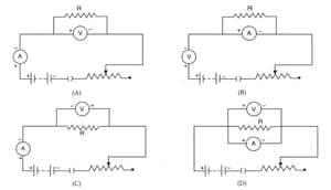
The correct circuit diagram for studying the dependence of current on the potential difference across a resistor is :
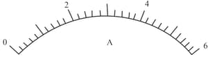
The least count of this ammeter is:


