
Consider the situation shown in figure. The wires and are made to slide on the rails with the same speed . Find the electric current in the resistor if both the wires move towards right and If moves towards left but moves towards the right.
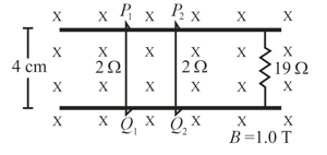
Suppose the resistor of the previous problem (described above) is disconnected. Find the current through in the two situations and of that problem.
Important Points to Remember in Chapter -1 - Electromagnetic Induction from H C Verma CONCEPTS OF PHYSICS [VOLUME 2] Solutions
1. Magnetic flux:
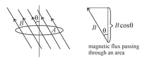
(i) Magnetic flux linking with the coil of area , when placed in a uniform magnetic field such that the area vector makes an angle with the magnetic field is
(ii) for non-uniform
(iii) S.I. unit: or
(iv) Dimensional formula:
(v) It is a scalar quantity.
2. Faraday's law of electromagnetic induction:
(i) An emf is induced whenever the magnetic flux linking with the circuit changes.
(ii) The magnitude of the induced emf in any circuit is proportional to the rate of change of the magnetic flux linking the circuit,
(iii) If the coil has turns, then the emf induced is , where is the flux linking with each turn of the coil.
(iv) , when the only magnetic field is variable.
(v) , when the only area is variable.
(vi) , when only is variable.
(vii) Maximum emf induced is,
(viii) If the coil rotates about its own axis in a perpendicular magnetic field, then the emf induced is zero.
3. Lenz's law:
(i) The direction of an induced emf is always such as to oppose the cause producing it.
(ii) Law of :
(iii) The negative sign indicates that the induced emf opposes the change of the flux.
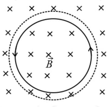
(iv) Induced current due to change in the field:
(a) If magnetic field strength increases with time as shown in the below figure, then the current induces in the anti-clockwise direction.
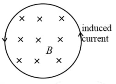
(b) If magnetic field strength decreases with time, then the current induces in the clockwise direction.
(v) Induced current due to change in the area:
(a) If the area increases, then the flux linkage increases, and hence current induces in the anti-clockwise direction to oppose the change in flux.
(b) If the area decreases, then the current induces in the clockwise direction.
4. Charge flowing in terms of change in flux:
, where is the resistance of the coil.
5. Induced EMF and current:
(i) Changing the magnetic field will produce a voltage in a coil, causing a current to flow.
(ii) To be completely accurate, if the magnetic flux through a coil is changed, a voltage will be produced. This voltage is known as the induced emf & the current flowing (if the loop is complete) is called induced current.
6. Motional emf:
(i) Emf in vector form is
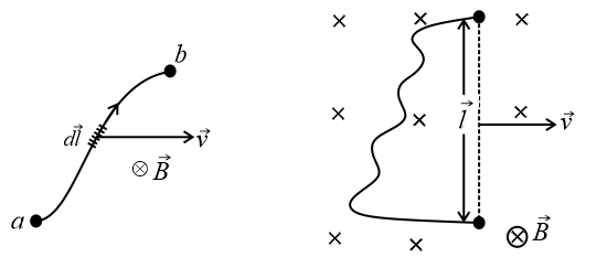
(ii) , where flux density, length of the conductor, velocity of the conductor, and angle between the direction of motion of conductor & field .
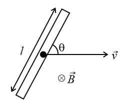
(iii) If the angle between or or is , then the emf induced is zero.
(iv) Maximum emf induced is at
7. Energy considerations when the rod is moving in a uniform magnetic field:
Consider a rod of length is moving with a velocity between the parallel rails placed in a uniform, perpendicular magnetic field . A resistance is connected to the ends of the rails as shown in the figure. Then,
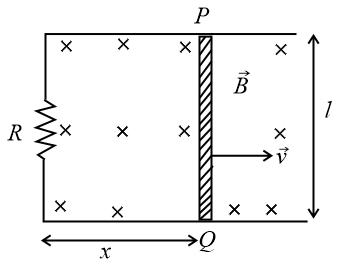
(i) Emf induced in the rod:
(ii) Current flowing through the circuit:
(iii) Power dissipated in the resistor:
(iv) Mechanical power supplied to the rod:
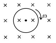
8. EMF induced in a rod rotating perpendicular to the magnetic field:
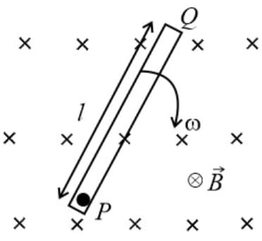
(a) When a rod of length is rotating in a uniform perpendicular magnetic field about one of its ends with an angular velocity , the emf induced in the rod is
(b) The direction of emf induced is decided by Fleming’s right-hand rule.
(c) Potential:
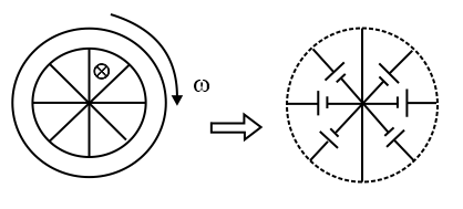
(ii) If a wheel of spokes each of length is rotating in a perpendicular magnetic field, then emf between centre of the wheel and its perimeter is,
(iii) If the rod is rotating about a point at distance from one end, then
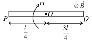
, and
9. Disc rotation in a magnetic field such that the axis of rotation is perpendicular to the magnetic field:
Consider a circular disc of radius is rotating with an angular velocity in a uniform magnetic field of induction . Then
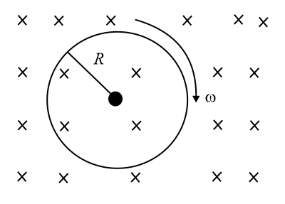
Emf induced between the centre and perimeter,
10. Self and Mutual Induction:
(i) Self-induction:
When a current flowing through a coil is changed the flux linking with its own winding changes & due to the change in linking flux with the coil an emf is induced which is known as self-induced emf & this phenomenon is known as self-induction. This induced emf opposes the cause of Induction.
(ii) Self-inductance:
(a) The property of the coil or the circuit due to which it opposes any change of the current coil or the circuit is known as Self-Inductance. It is also called electrical inertia. Its S.I. unit is .
(b) Let be the flux linking with each turn, and be the number of turns in the coil, then the total flux linkage is,
(c) Coefficient of self-inductance, for , where current in the circuit, magnetic flux linked with the circuit due to the current .
(d) depends only on (i) the shape of the loop & (ii) medium.
(e) self-induced emf, (if is constant)
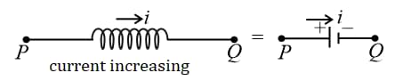
(f) If the current is flowing from to and increasing with time, then
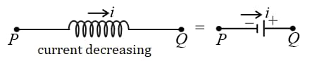
(g) If the current is flowing from to and increasing with time, then
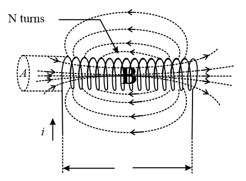
(h) Self-inductance of a solenoid, , where area of cross-section of the solenoid, magnetic permeability of the core material, number of turns in the solenoid per unit length, and current in the solenoid.
(i) Self-inductance of a circular coil carrying current , having radius and number of turns is given by
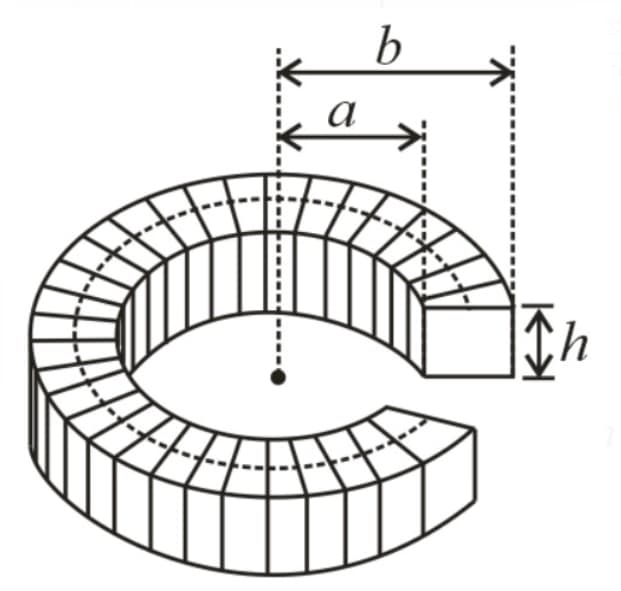
(j) Self-inductance of a toroidal solenoid:
Consider a toroidal coil of internal radius , and external radius with a thickness having turns. The self-inductance of this coil is
(iii) Mutual Induction:
(a) If two electric circuits are such that the magnetic field due to a current in one is partly or wholly linked with the other, the two coils are said to be electromagnetically coupled circuits.
(b) Any change of current in one produces a change of magnetic flux in the other & the latter opposes the change by inducing an emf within itself. This phenomenon is called mutual induction.
(c) The induced emf in the later circuit due to a change of current in the former is called mutually induced emf. The circuit in which the current is changed is called the primary & the other circuit in which the emf is induced is called the secondary.
(iv) Mutual-Inductance:
(a) The coefficient of mutual induction (mutual inductance) between two electromagnetically coupled circuits is the magnetic flux linked with the secondary per unit current in the primary.
(b) Mutual inductance
(c) mutually induced emf, (where is constant)
(d) depends on the geometry of loops, medium, orientation & distance between the loops.
(e) If two coils of self-inductances and are wound over each other, then the mutual inductance , where is called coupling constant. lies between and .
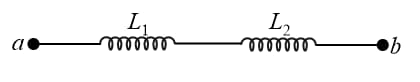
(f) Series combination same, in the ratio of inductance, in the ratio of inductance, in the ratio of inductance.
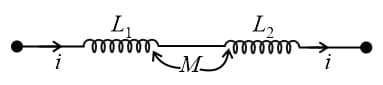
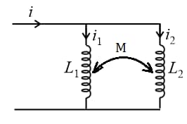
(g) For two coils wound in the same direction connected in series and mutually interacting with each other,
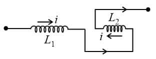
(h) For two coils wound in opposite direction connected in series and mutually interacting with each other,
(i) For a parallel combination of inductors:
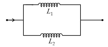
(j) Two coils in parallel and mutually interacting with each other,
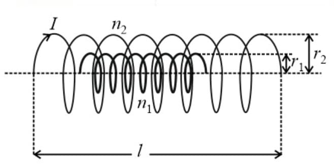
(k) Mutual inductance between two co-axial solenoids,
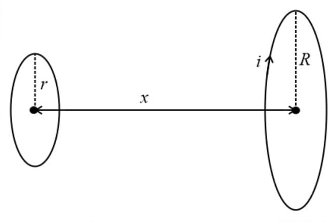
(l) Mutual inductance between two co-axial circular coils separated by some distance:
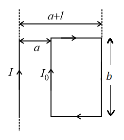
(m) Mutual inductance between the infinite straight wire and a rectangular coil separated by some distance is,
11. Induced electric field:
(i) An emf is induced in a closed loop where magnetic flux is varied.
(ii) The induced electric field is not a conservative field because, for the induced electric field, the line integral around a closed path is non-zero.
12. Transformer:
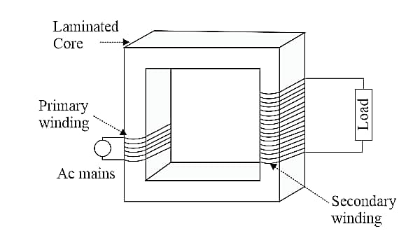
(i) For an ideal transformer,
(ii) Efficiency,
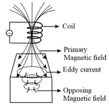
13. Eddy Current:
(i) An eddy current is a current set up in a conductor in response to a changing magnetic field.
(ii) Eddy currents flow in closed loops in a plane perpendicular to the magnetic field.
(iii) By Lenz’s law, the current swirls in such a way as to create a magnetic field opposing the change.
(iv) For this to occur in a conductor, electrons swirl in a plane perpendicular to the magnetic field.
(v) Because of the tendency of eddy currents to oppose, eddy currents cause a loss of energy.
(vi) Eddy currents transform more useful forms of energy, such as kinetic energy, into heat, which is not generally useful.
14. Super conduction loop in a magnetic field:
(i) Reistance . So, emf induced . Therefore, constant.
(ii) Thus, in a superconducting loop flux never changes, or it opposes .
15. Magnetic energy stored in an inductor:
Energy stored in an inductor of inductance and carrying a current is,
16. Magnetic energy density:
Magnetic energy store per unit volume in terms of magnetic field induction is
17. The energy between two interacting coils:
The total energy stored in two coils with inductances , and mutual inductance , if they carry currents and respectively is,
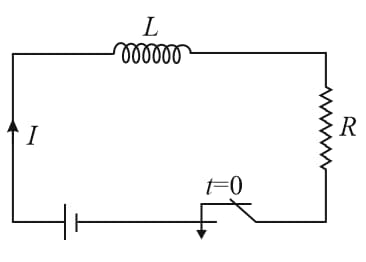
18. LR DC circuit:
(i) Growth of a current in an circuit:
(a) Current at any time is
(b) The time constant of the circuit
(c) Final steady current
(d) Inductor behaves as an open circuit at [If ]
(e) Inductor behaves as a short circuit at always.
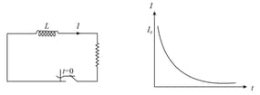
(ii) Decay of Current:
(a) Initial current through the inductor
(b) Current at any instant,
19. Alternating currents:
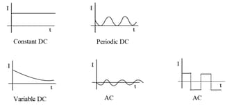
(i) A current that changes its direction periodically is called alternating current (). If a current maintains its direction constant it is called direct current ().
(ii) Average value:
(iii) RMS value:
(iv) For a sinusoidal voltage
(v) For a sinusoidal current
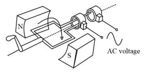
20. AC generator:
An generator is an electric generator that converts mechanical energy into electrical energy in form of an alternative emf or alternating current. generators work on the principle of electromagnetic induction.
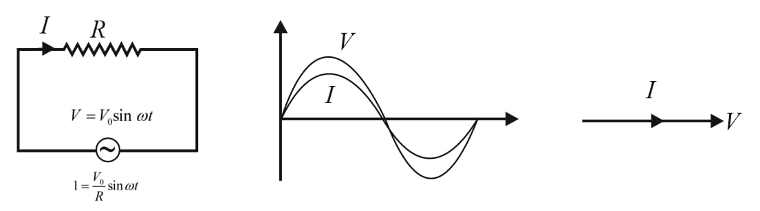
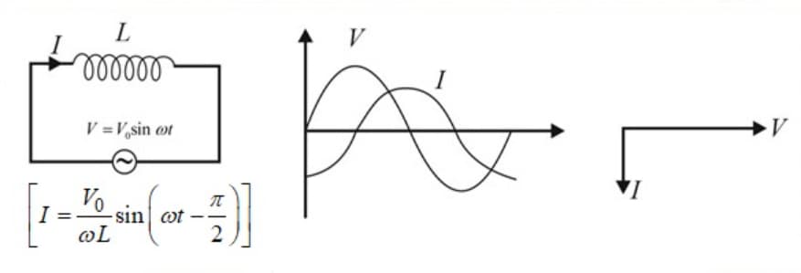
21. AC circuit:
 |
 |
 |
(i) In a pure resistor, current and voltage are in phase.
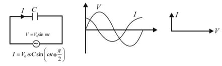
(ii) In a pure capacitor, the current leads the voltage by
(iii) In a pure inductor, the current lags the voltage by
22. Reactance and Impedance:
(i) is called inductive reactance and is denoted by
(ii) is called capacitive reactance and is denoted by
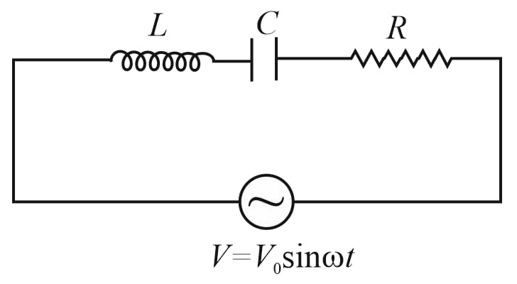
23. Series LCR Circuit:
Consider a series series circuit with resistance , inductive reactance , and capacitive reactance .
(i) Impedance,
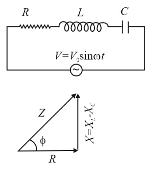
(ii) Applied voltage in terms of voltages across the components,
24. Power in AC Circuits and Wattless current:
(i) Average power consumed in a cycle
(ii) , here is called a power factor.
(iii) The current in circuit is said to be wattless current when the average power consumed in such circuit corresponding to zero such current is also called idle current.
25. Wattless current:
In an circuit, if the average power consumed is zero, then the current is called a wattless current. Its formula is , where is the phase difference between current and voltage applied.
26. Resonance:
(i) At resonance:
(ii) Resonant frequency is , where is the inductance, and is capacitance.
(iii) Nature of the circuit is resistive.
(iv) Current in the circuit is maximum, i.e.,
(v) Power consumed at resonance is
27. Bandwidth:
The bandwidth of series circuit of resistance , inductance , and Capacitance is
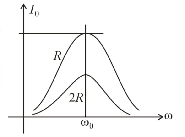
As the resistance increases, peak current decreases, and the bandwidth increases.
28. Quality factor:
factor (also known as a Quality factor or -factor) is defined as a dimensionless parameter that describes the underdamped condition of an oscillator or resonator.
The quality factor of series RLC circuit of resistance , inductance , and Capacitance is
29. LC oscillations:
(i) , where
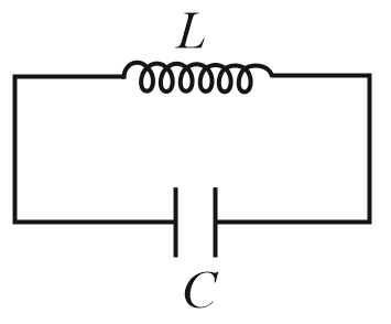
(ii) Energy
(iii) Comparison of LC oscillations with SHM of spring:
30. Comparison of damped mechanical & electrical systems:
(i) Series LCR circuit:
Consider a resistance , inductnace , and capacitance are connected in series. Let be the charge on the capacitor at time . Then,
compare with the mechanical damped system equation,
, where damping coefficient.
| Mechanical system | Electrical systems (series RLC) |
| Displacement | Charge |
| Driving force | Driving voltage |
| Kinetic energy | Electromagnetic energy of moving charge |
| Potential energy | The energy of the static charge |
| Mass | Inductance |
| Power | Power |
| Damping | Resistance |
| Spring constant |
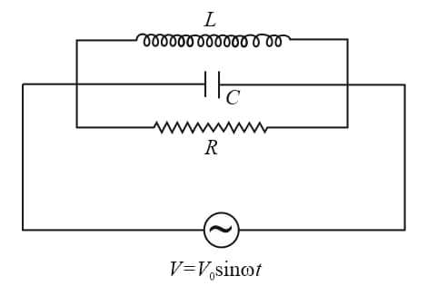
(ii) Parallel LCR circuit:
(a) Consider a resistance , inductnace , and capacitance are connected in parallel. Let be the charge on the capacitor at time . Then,
(b) Displacement Flux linkage
(c) Velocity Voltage
(d) Mass Capacitance
(e) Spring constant Reciprocal Inductance
(f) Damping coefficient Reciprocal resistance ; Driving force Current


