Figure shows the circuit diagram of a potentiometer for determining the emf of a cell of negligible internal resistance.

What is the purpose of using high resistance ?
Important Questions on Current Electricity
Figure shows the circuit diagram of a potentiometer for determining the emf of a cell of negligible internal resistance.
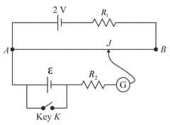
How does the position of balance point change when the resistance is increased?
Figure shows the circuit diagram of a potentiometer for determining the emf of a cell of negligible internal resistance.

Why cannot the balance point be obtained,
(a) when the emf E is greater than , and
(b) when the key is closed?
A series combination of a resistor and resistor, is connected across a battery of emf and
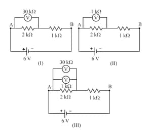
negligible internal resistance. The potential drop, across the resistor, is measured by (i) a voltmeter (ii) a voltmeter and (iii) both these voltmeters connected across it, as shown in Fig. . If the voltmeter readings in the three cases are and respectively, arrange these readings in descending order.
How will the three readings compare with one another if the potential drops were measured across the series combination of the and the resistor i.e., across the series combination of the and the resistor i.e., across the points and ?
For the circuit shown in Figure , would the balancing length increase, decrease or remain the same, if (i) is decreased, (in each case) in the rest of the circuit? Justify your answer in each case.
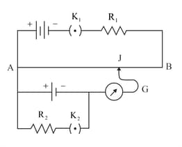
For the circuit shown in Figure , would the balancing length increase, decrease or remain the same, if is increased without any other change, (in each case) in the rest of the circuit? Justify your answer in each case.

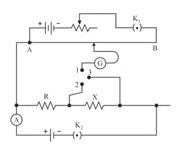
A potentiometer circuit is set up as shown in Fig. . The potential gradient across the potentiometer wire is and the ammeter present in the circuit reads , when the two way key is completely switched off. The balance points, when the key between the terminals (i) 1 and 2 (ii) 1 and 3, is plugged in, are found to be at lengths and respectively. Find the values of and
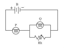
The circuit shown in the Fig. contains a battery , a rheostat and identical lamps and .What will happen to the brightness of the lamps, if the resistance through the rheostat is increased? Give reasons.
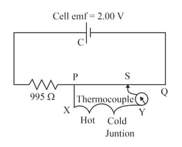
The circuit diagram shows the use of a potentiometer to measure a small emf produced by a thermocouple connected between and . The cell C, of emf , has negligible internal resistance. The potentiometer wire is m long and has resistance . The balance point is found to be from . Calculate the value of emf generated by the thermocouple.