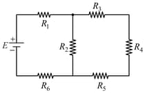
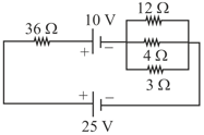
Find the potential difference across the resistance, i.e., for the following circuit.
Important Questions on Current Electricity
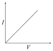
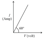
characteristic of a copper wire of length and area of cross-section is shown in figure. The slope of the curve becomes
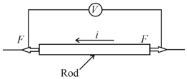
As shown in the schematic below, a rod of uniform cross-sectional area and length is carrying a constant current through it and voltage across the rod is measured using an ideal voltmeter. The rod is stretched by the application of a force .
Which of the following graphs would show the variation in the voltage across the rod as function of the strain when the strain is small. Neglect Joule heating.
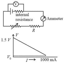
If is almost zero, identify the correct statement:
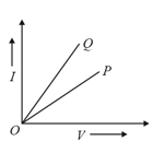
graphs for two different electrical appliances and are shown in the diagram. If and be the resistances of the devices, then
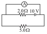
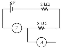
An ideal ammeter is connected to a battery as shown in the figure. The currents through the resistor and the resistor are, respectively
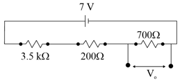
Find the voltage and current passing through the resistor shown in the following circuit
What is the current in the resistor when switch is open and switch is closed in the given circuit?

In the circuit shown below, a student performing Ohm's law experiment accidentally puts the voltmeter and the ammeter as shown in the circuit below; the reading in the voltmeter will be close to
For the circuit shown, the value of current at time will be ______ .
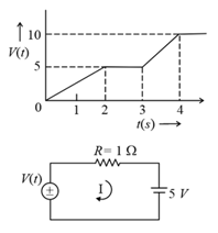
[Voltage distribution is shown by Fig. and the circuit is shown in Fig. ]
The current through the resistor in the given circuit is
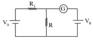
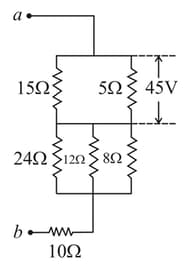
Find the potential difference between and , as shown in the below circuit.
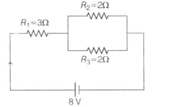
In the figure shown, what is the current (in ampere) drawn from the battery? You are given: