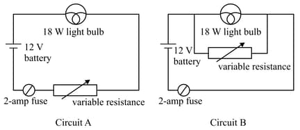
Following two circuits and are designed to control brightness of an bulb. Each circuit consists of a light bulb rated at and , a variable resistor, an ideal battery and a fuse with negligible resistance.
Important Questions on Current Electricity
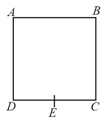
( is mid-point of arm )
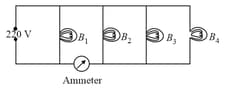
Four bulbs , , and of each are connected to main as shown in the figure. The reading in an ideal ammeter will be
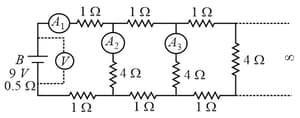
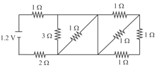
A battery with an internal resistance of is connected across an infinite network, as shown in the figure. All ammeters and voltmeter are ideal.
Choose the correct statement.
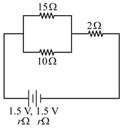
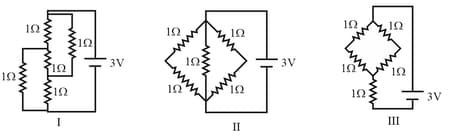
In the given circuit, an ideal voltmeter connected across the resistance reads . The internal resistance , of each cell is:
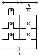
Six similar bulbs are connected as shown in the figure with a DC source of emf , and zero internal resistance.
The ratio of power consumption by the bulbs when all are glowing and in the situation when two from section and one from section are glowing will be,
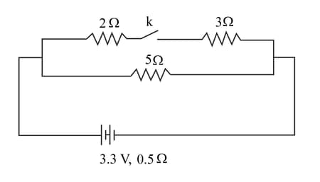
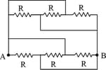
The diagram above shows a circuit with the key k open.
Calculate the resistance of the circuit when the key k is closed.
Calculate the current drawn from the cell when the key k is closed.
The variation of terminal potential difference with current flowing through as cell is as shown
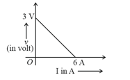
The and internal resistance of the cell are
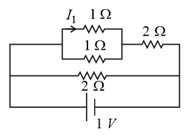
In the given circuit, the current through resistor is