Give circuit symbol, logical operation, truth table, and Boolean expression of AND, OR, NOT, NAND, NOR and EX-OR gates.
Important Questions on Semiconductor Electronics: Materials, Devices and Simple Circuits
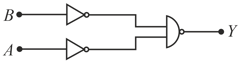
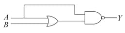
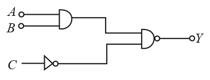
Identify the logic operation carried out.
The truth table given below corresponds to logic gate.
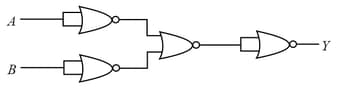
The truth table for the following logic circuit is :
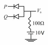
In the given circuit, the input voltages at and could be either or . Use the fact that a diode under forward bias is a short circuit, and under reverse bias is an open circuit. The truth table of the circuit will be that of
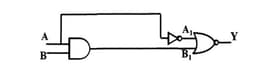
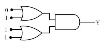
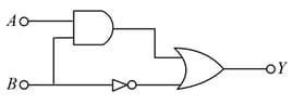
Refer the given circuit diagram. Using the given inputs, write the truth table to get the output Y :
| A | B |
| 0 | 0 |
| 0 | 1 |
| 1 | 0 |
| 1 | 1 |
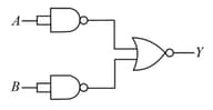
The output of the given combination gates represents:
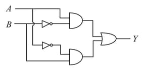
For the following logic circuit,
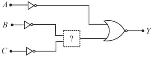
for
for
for
The logic gate in the question-marked box will be,
Write value of output in diagram.
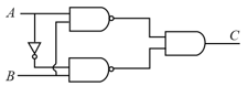
The truth table for the given logic circuit is:
In the circuit the output becomes zero for the inputs
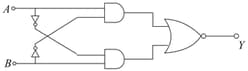
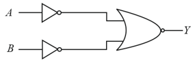
Find the truth table for the function of and represented in the following figure.
The truth table for the given logic circuit is
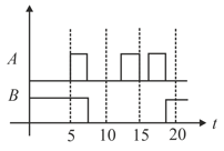
Identify the correct output signal in the given combination of gates (as shown ) for the given inputs