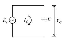
In a circuit consisting of a capacitance and a generator with alternating emf, and are the voltage and current. Correct phasor diagram for such circuit is
Important Questions on Electromagnetic Induction and Alternating Currents
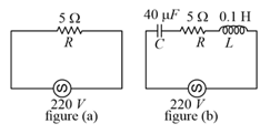
Two circuits are shown in figure and . At a frequency of _______ the average power dissipated in one cycle will be the same in both the circuits.
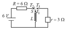
Consider an electrical circuit containing a two way switch Initially is open and then is connected to As the current in attains a maximum value of steady-state level, is disconnected from and immediately connected to Potential drop across resistor immediately after is connected to is (Round off to the Nearest Integer)
In the given figure the magnetic flux through the loop increases according to the relation , where is in milliwebers and is in seconds. The magnitude of current through resistor at is _____

A conducting bar of length is free to slide on two parallel conducting rails as shown in the figure.
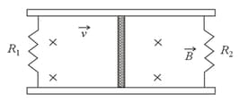
Two resistors and are connected across the ends of the rails. There is a uniform magnetic field pointing into the page. An external agent pulls the bar to the left at a constant speed .
The correct statement about the directions of induced currents and flowing through and respectively is :
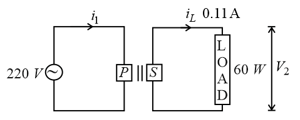
For the given circuit, comment on the type of transformer used :