EASY
Earn 100

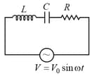
In a circuit current lags behind the voltage by π3, the elements in the circuit are-

50% studentsanswered this correctly

Important Questions on Alternating Current

MEDIUM
An arc lamp requires a direct current of 10 A at 80 V to function. If it is connected to a 220 V (rms), 50 Hz AC supply, the series inductor needed for it to work is close to:
HARD
A sinusoidal voltage of peak value 283 V and angular frequency 320 s-1 is applied to a series LCR circuit. Given that R=Ω, L=25 mH and C=1000 μF. The total impedance and phase difference between the voltage across the source and the current will respectively be-
EASY
When the rms voltages V L , V C and V R are measured respectively across the inductor L, the capacitor C and the resistor R in a series LCR circuit connected to an AC source, it is found that the ratio V L : V C : V R =1:2:3. If the rms voltage of the AC source is 100V, then V R is close to :
EASY
A series R-C circuit is connected to an alternating voltage source. Consider two situations:

i. When capacitor is air filled.

ii. When capacitor is mica filled.

Current through resistor is i and voltage across capacitor is V then:
MEDIUM
A resistance R draws power P when connected to an AC source. If an inductance is now placed in series with the resistance, such that the impedance of the circuit becomes Z , the power drawn will be:
MEDIUM
A circuit connected to an ac source of emf e=e0sin100t with t in seconds, gives a phase difference of π4 between the emf  e and current i . Which of the following circuits will exhibit this?
HARD

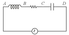
An AC voltmeter connected between points A and B in the circuit below reads 36 V. If it is connected between A and C, the reading is 39 V. The reading when it is connected between B and D is 25 V. What will the voltmeter read when it is connected between A and D? ( Assume that the voltmeter reads true RMS voltage values and that the source generated a pure AC.)

Question Image

EASY
Choose the wrong statement for the pure inductive circuit.
HARD

If the input voltage Vi to the circuit below is given by Vit=Acos2πft, the output voltage is given by Vot=Bcos2πft+ϕ.

Question Image

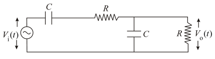
Which one of the following four graphs best depict the variation of ϕ vs f?

EASY
Out of the following graphs, which graph shows the correct relation (graphical representation) for LC Parallel resonant circuit?
EASY
A small signal voltage Vt=V0sinωt is applied across an ideal capacitor C:
EASY
A bird sitting on a single high tension wire does not get electrocuted because
MEDIUM
An alternating voltage V(t)=220sin100πt volt is applied to a purely resistive load of 50 Ω . The time taken for the current to rise from half of the peak value to the peak value is:
EASY
A series LR circuit is connected to a voltage source with Vt=V0sinωt . After a very large time, current It behaves as t0LR:
EASY
An inductor of inductance L and resistor R are joined together in series and connected by a source of frequency ω. The power dissipated in the circuit is
HARD
An inductance coil has a reactance of 100 Ω . When an AC signal of frequency 1000 Hz is applied to the coil, the applied voltage leads the current by 45°. The self-inductance of the coil is
HARD
750 Hz, 20 Vrms source is connected to a resistance of 100 Ω, an inductance of 0.1803 H and a capacitance of 10 μF all in series. The time in which the resistance (heat capacity  2 J/°C ) will get heated by 10°C. (assume no loss of heat to the surroundings) is close to :
HARD
A voltage VPQ=V0cosωt (where, V0 is a real amplitude) is applied between the points P and Q in the network shown in the figure. The values of capacitance and inductance are C=1ωR3 and L=R3ω. Then, the total impedance between P and Q is
Question Image
MEDIUM
An alternating voltage V=V0 sin ωt is connected to a capacitor of capacity C through an A.C. ammeter of zero resistance. The reading of ammeter is
MEDIUM
For the LCR circuit, shown here, the current is observed to lead the applied voltage. An additional capacitor C , when joined with the capacitor C present in the circuit, makes the power factor of the circuit unity. The capacitor C , must have been connected in:
Question Image