
In an house hold electric circuit,
Important Questions on Electromagnetic Induction and Alternating Currents
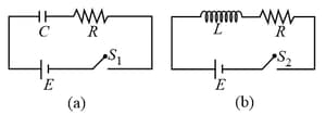
i. When capacitor is air filled.
ii. When capacitor is mica filled.
Current through resistor is and voltage across capacitor is then:
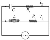
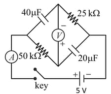
In the above circuit, and Current in path is and in path it is The voltage of AC source is given by, volts. The phase difference between and is:
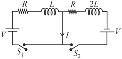
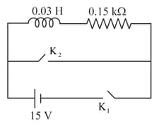
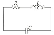
In the circuit shown below, the key is pressed at time . Which of the following statement(s) is(are) true?
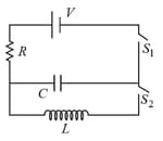
An inductor and a resistor are connected in series to a battery of E.M.F. in a circuit shown below. The key has been kept closed for a long time. Then at , is opened and key is closed simultaneously. At , the current in the circuit will be :
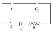
In the following circuit the switch is closed at . The charge on the capacitor as a function of time will be given by
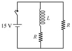
In the figure shown, a circuit contains two identical resistors with resistance and an inductance with An ideal battery of is connected in the circuit. What will be the current through the battery long after the switch is closed?
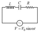
If a student plots graphs of the square of maximum charge on the capacitor with time (t) for two different values and of L then which of the following represents this graph correctly? (plots are schematic and not drawn to scale)


