In figure, assume that and . If the voltmeter resistance is , what percent error does it introduce into the measurement of the potential difference across ? Ignore the presence of the ammeter.
Important Questions on Circuits
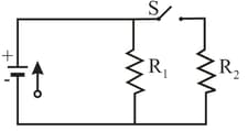
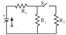
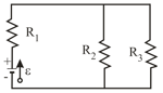
The resistances in figures (a) and (b) are all , and the batteries are ideal batteries. (a) When switch in figure (a) is closed, what is the change in the electric potential across resistor or does remain the same? (b) When switch in figure (b) is closed, what is the change in across resistor or does remain the same?
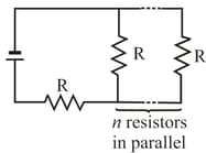
In figure an array of parallel resistors is connected in series to a resistor and an ideal battery. All the resistors have the same resistance. If an identical resistor were added in parallel to the parallel array, the current through the battery would change by What is the value of ?
In the following figure, the resistances are and the battery is ideal. What value of maximizes the dissipation rate in resistance ?
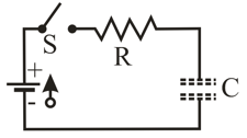
A capacitor with an initial potential difference of is discharged through a resistor when a switch between them is closed at At the potential difference across the capacitor is . (a) What is the time constant of the circuit? (b) What is the potential difference across the capacitor at
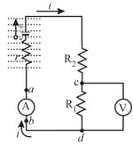
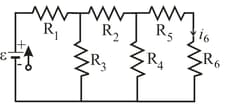
In the following figure, the current in resistance is and the resistances are and What is the emf of the ideal battery?
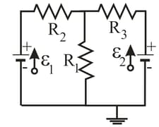
In the following figure, , and . One point of the circuit is grounded What are the (a) size and
(b) direction (up or down) of the current through resistance the (c) size and (d) direction (left or right) of the current through resistance and the (e) size and (f) direction of the current through resistance (g) What is the electric potential at point ?
Switch S in the following figure is closed at time to begin charging an initially uncharged capacitor of capacitance through a resistor of resistance . At what time is the potential across the capacitor equal to that across the resistor?