In following diagram boxes may contain resistor or battery or any other element.
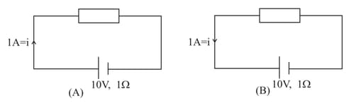
Then determine in each case
(a) of battery.
(b) Battery is acting as a source or load.
(c) Potential difference across each battery.
(d) Power input to the battery or output by the battery.
(e) The rate at which heat is generated inside the battery.
(f) The rate at which the chemical energy of the cell is consumed or increased.
(g) Potential difference across the box
(h) Electric power output across the box.
Important Questions on Current Electricity
(a) A car has a fresh storage battery of emf and internal resistance . If the starter draws a current of , what is the terminal voltage of the battery when the starter is on?
(b) After long use, the internal resistance of the storage battery increases to . What maximum current can be drawn from the battery? Assume the emf of the battery remain unchanged.
(c) If the discharged battery is charged by an external emf source, is the terminal voltage of the battery during charging greater or less than its emf ?
electric heater is to be used with supply.
(a) What is the current in the heater?
(b) What is its resistance?
(c) What is the power dissipated in the heater?
(d) How much heat in calories is produced per second?
(e) How many grams of water at will be converted per minute into steam at ?
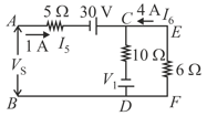
In following circuit potential at point is zero then determine
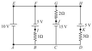
(a) Potential at each point.
(b) Potential difference across each resistance.
(c) Identify the batteries which act as a source.
(d) Current in each battery.
(e) Which resistance consumes maximum power?
(f) Which battery consume or gives maximum power?
For the circuit shown in figure, find the voltage across resistor and the current passing through it.
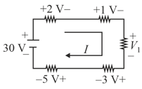
For the circuit shown in the figure, determine the unknown voltage drop .
A resistor develops of thermal energy in when a current of is passed through it. (a) Find its resistance. (b) If the current is increased to , what will be the energy developed in .
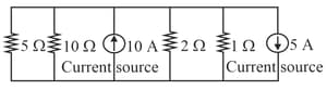
Find the current in resistance, , and source voltage in the circuit shown in figure.