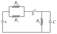
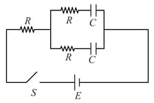
In the circuit shown (figure), the switch is closed first and is kept closed for a long time. Now, is closed, Just after that instant, the current thought is,
Important Questions on Electric Current and Circuits
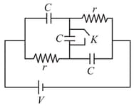
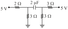
Each resistor in the following circuit (figure) has a resistance of and the capacitors have a capacitance of . The battery voltage is . The voltage across the resistor in the following circuit in steady state is,
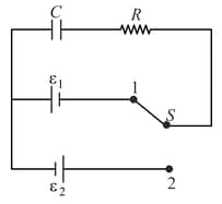
Initially, switch is connected to position for a long time (figure). The net amount of heat generated in the circuit after it is shifted to position is
The switch in the circuit diagram (figure) is closed at . The charge on capacitors at any time is,
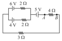
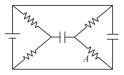
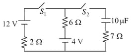
The charge on the capacitor in steady-state in the circuit shown (figure) is
In the circuit shown (Figure), if switches , and have been closed for a long time, then the charge on the capacitor
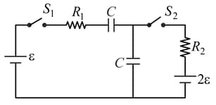
The circuit shown in figure consists of a battery of emf, , a capacitor of capacitance and three resistors of values, , and . Initially, the capacitor is completely uncharged and the switch is open. The switch is closed at . Then,