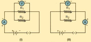
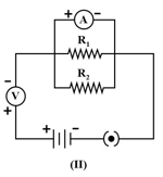
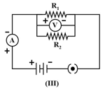
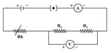
In the experiment on finding the equivalent resistance of two resistors, connected in parallel, two students connected the ammeter in two different ways as shown in given circuits and . The ammeter has been correctly connected in:
Important Questions on Electricity
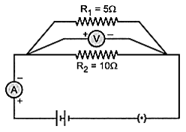
In the experiment on finding the equivalent resistance of two resistors, connected in parallel, the voltmeter has been correctly connected in:
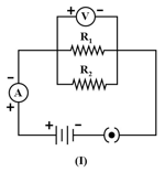
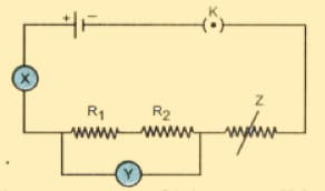
The given circuit diagram shows the experimental arrangement of different circuit components for determination of equivalent resistance of two resistors connected in series. The components X, Y and Z are shown in the circuit, respectively represent:
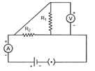
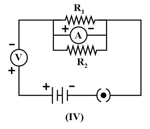
For the experiment “to find the equivalent resistance of the two given resistors connected in parallel” the following circuit was drawn by a student:
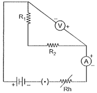
The teacher pointed out the possibility of the following faults:
The ammeter was not correctly connected in the circuit
The voltmeter was not correctly connected in the circuit
The resistors and were not correctly connected in parallel
The rheostat and the key were not correctly connected in the circuit.
The two faults pointed out correctly by the teacher, are
The current flowing through a resistor connected in an electric circuit and the potential difference developed across the ends of it are as shown in the diagrams.
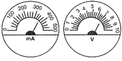
The value of the resistance of the resistor used in ohm is:
In an experiment to study the dependence of current on potential difference across a resistor, a student obtained the graph as shown in the diagram.
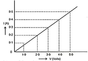
The value of resistance of the resistor is:
In the circuit given below, on plugging the key the voltmeter reads but ammeter reads . The resistance of the combination is: