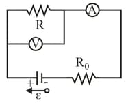
In the following figure, a voltmeter of resistance and an ammeter of resistance are being used to measure a resistance in a circuit that also contains a resistance and an ideal battery of emf . Resistance is given by , where is the voltmeter reading and is the current in resistance . However, the ammeter reading is not but rather which is plus the current through the voltmeter. Thus, the ratio of the two meter readings is not but only an apparent resistance . If , what are (a) the ammeter reading, (b) the voltmeter reading, and (c) ? (d) If is increased, does the difference between and increase, decrease, or remain the same?
Important Questions on Circuits
A resistor and a capacitor are connected in series with an ideal battery of emf . At after the connection is made, what is the rate at which
(a) the charge of the capacitor is increasing?
(b) energy is being stored in the capacitor?
(c) thermal energy is appearing in the resistor?
(d) energy is being delivered by the battery?
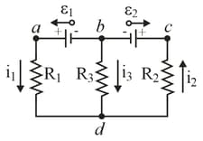
In the figure, the ideal batteries have EMFs and and the resistances are and If the potential at is what is it at ?
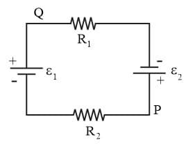
Figure shows the circuit of a flashing lamp, like those attached to barrels at highway construction sites. The fluorescent lamp (of negligible capacitance) is connected in parallel across the capacitor of an circuit. There is a current through the lamp only when the potential difference across it reaches the breakdown voltage . Then the capacitor discharges completely through the lamp and the lamp flashes briefly. For a lamp with breakdown voltage wired to a ideal battery and a capacitor, what resistance is needed for two flashes per second?
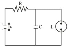
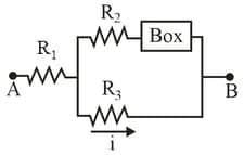
Figure shows a section of a circuit. The resistances are and and the indicated current is The electric potential difference between points and that connect the section to the rest of the circuit is (a) Is the device represented by absorbing or providing energy to the circuit, and (b) at what rate?
In the Fig., what is the potential difference between the points and if and and the battery is ideal?