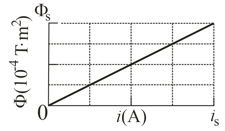
In the given figure (a), the inductor has turns and the ideal battery has an emf of . Figure (b) gives the magnetic flux through each turn versus the current through the inductor. The vertical axis scale is set by and the horizontal axis scale is set by . If switch is closed at time , at what rate will the current be changing at ? Where is the time constant.
(a)
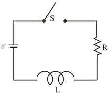
(b)
Important Questions on Induction and Inductance
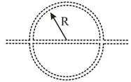
In the given figure, wire forms a closed circular loop, of radius and resistance . The circle is centred on a long straight wire, at time , the current in the long straight wire is rightward. Thereafter, the current changes according to . (The straight wire is insulated, so there is no electrical contact between it and the wire of the loop). What is the magnitude of the current induced in the loop at times ?
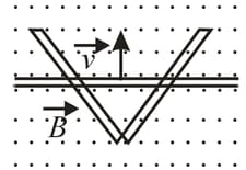
In given figure, two straight conducting rails form a right angle. A conducting bar in contact with the rails starts at the vertex at time and moves with a constant velocity of along them. A magnetic field with is directed out of the page. Calculate the flux through the triangle formed by the rails and bar at and the emf around the triangle at that time. If the emf is where and are constants, what is the value of
A solenoid having an inductance of is connected in series with a resistor.
If a battery is connected across the pair, how long will it take for the current through the resistor to reach of its final value?
What is the current through the resistor at time ?
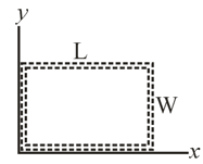
In the given figure, a wire loop of lengths and lies in a magnetic field . What are the
Magnitude of induced EMF and direction (clockwise or counterclockwise or none if ) of the emf induced in the loop, if ? What are and the direction, if What are and the direction, if ? What are and the direction, if ? What are and the direction, if ?