
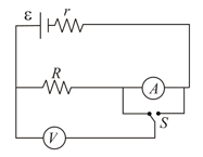
The emf and the internal resistance of the battery shown in figure are and , respectively. The external resistance is . The resistances of the ammeter and voltmeter are and , respectively. (a) Find the readings of the two meters. (b) The switch is thrown to the other side. What will be the readings of the two meters now?
Important Questions on Current Electricity
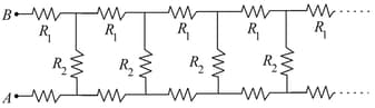
Consider an infinite ladder network shown in the figure. A voltage is applied between points and . If the voltage is halved after each section, find the ratio . Suggest a method to terminate it after a few sections without introducing much error in attenuation.
In a potentiometer circuit, two wires of same material of resistivity , one of radius of cross-section and other of radius of cross-section are joined in series. They are of length , respectively. This combination acts as the potentiometer wire of length . The emf of the cell in the primary circuit is and internal resistance is . This cell is connected to the potentiometer wire by a conducting wire of negligible resistance with positive terminal of the cell connected to one end (call it ) of longer wire. The negative terminal of the cell is connected to one end of the smaller wire. The remaining ends of the two wires are joined together. Find:
(i) The maximum voltage which can be balanced on the potentiometer wire.
(ii) The length, measured from point A, where cell of emf will balance.
(iii) If positive terminal of cell of emf and internal resistance is connected to point and other terminal is joined to the junction of the two wires, then find the current through this cell.
A rod of length and cross-section area lies along the x-axis between and . The material obeys Ohm's law and its resistivity varies along the rod according to, The end of the rod at is at a potential and it is zero at
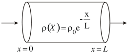
(a) Find the total resistance of the rod and the current in the wire.
(b) Find the electric potential in the rod as a function of .
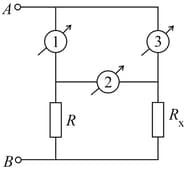
In the circuit shown the three ammeters (marked as 1, 2, 3) are identical, each have a resistance . Between points and there is a constant potential difference of . The first and second ammeter read and , respectively.
(a) What is the reading of third ammeter?
(b) Calculate value of resistance .
(c) Investigate what happens to current if the value of is changed. Show approximately graphical variation of vs .
Note : Reading of ammeter implies current through branch of ammeter.
This question is about a closed electrical black box with three terminals and as shown. It is known that the electrical elements connecting the points inside the box are resistances (if any) in delta formation. A student is provided a variable power supply, an ammeter and a voltmeter. Schematic symbols for these elements are given in part (a). She is allowed to connect these elements externally between only two of the terminals ( or or ) at a time to form a suitable circuit.
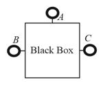
(a) Draw a suitable circuit using the above elements to measure the voltage across the terminals and and the current drawn from power supply as per Ohm’s law.
(b) She obtains the following readings in and for the three possible connections to the black box.
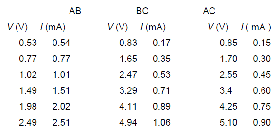
In each case plot (on Y-axis) (on X-axis) on the graph papers provided. Preferably use a pencil to plot. Calculate the values of resistances from the plots. Show your calculations below for each plot clearly indicating graph number.
(c) From your calculations above draw the arrangement of resistances inside the box indicating their values.


