
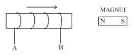
The following diagram in Figure shows a coil of several turns of copper wire near a magnet NS. The coil is moved in the direction of arrow shown in the diagram.
In what direction does the induced current in coil flow?

Important Questions on Electro-Magnetism
The following diagram in Figure shows a coil of several turns of copper wire near a magnet NS. The coil is moved in the direction of arrow shown in the diagram.
Name the law used to arrive at the conclusion.

The following diagram in Figure shows a coil of several turns of copper wire near a magnet NS. The coil is moved in the direction of arrow shown in the diagram.
How would the current in coil be altered if (a) the coil has twice as many turns, (b) the coil was made to move three times as fast?
The following diagram in Figure shows a fixed coil of several turns connected to a centre zero galvanometer and a magnet which can move in the direction shown in the diagram.

Describe the observation in the galvanometer if the magnet is moved rapidly.
The following diagram in Figure shows a fixed coil of several turns connected to a centre zero galvanometer and a magnet which can move in the direction shown in the diagram.

Describe the observation in the galvanometer if the magnet is kept still after it has moved into the coil.
The following diagram in Figure shows a fixed coil of several turns connected to a centre zero galvanometer and a magnet which can move in the direction shown in the diagram.
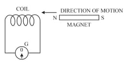
Describe the observation in the galvanometer if the magnet is then rapidly pulled out of the coil.
The following diagram in Figure shows a fixed coil of several turns connected to a centre zero galvanometer and a magnet which can move in the direction shown in the diagram.

How would the observation in part (a) alter if a more powerful magnet is used?
The following diagram in Figure shows a coil connected to a sensitive centre-zero galvanometer and a coil connected to a battery through a switch

Describe the observation when the switch is (i) closed suddenly, (ii) then kept closed, (iii) finally opened.
The following diagram in Figure shows a coil connected to a sensitive centre-zero galvanometer and a coil connected to a battery through a switch
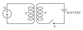
Name and state the law which explains the above observations.


