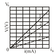
The ideal battery in the given figure (a) has emf . Plot in the figure (b) gives the electric potential difference that can appear across resistor 1 versus the current in that resistor when the resistor is individually tested by putting a variable potential across it. The scale of the axis is set by , and the scale of the axis is set by . Plots and are similar plots for resistors and , respectively, when they are individually tested by putting a variable potential across them. What is the current in resistor in the circuit of figure a?
Important Questions on Circuits
(a) In Fig., what current does the ammeter read if (ideal battery), and
(b) The ammeter and battery are now interchanged. Show that the ammeter reading is unchanged.
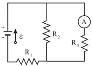
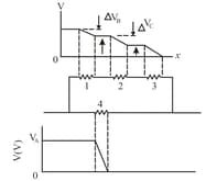
Figure shows a circuit of four resistors that are connected to a larger circuit. The graph below the circuit shows the electric potential as a function of position along the lower branch of the circuit, through resistor the potential . The graph above the circuit shows the electric potential versus position along the upper branch of the circuit, through resistors and the potential differences are and Resistor has a resistance of and same potential drop as resistor What is the resistance of (a) resistor and (b) resistor ?
(a) In electron-volts, how much work does an ideal battery with a emf do on an electron that passes through the battery from the positive to the negative terminal?
(b) If electrons pass through each second, what is the power of the battery in watts?
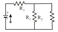
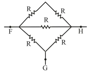
Figure shows five resistors. Calculate equivalent resistance between points (a) and and (b) and . (Hint: For each pair of points, imagine that a battery is connected across the pair.
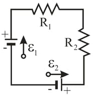
In figure, the ideal batteries have emfs , and resistances are and . What are (a) the current (b) dissipation rate in resistor (c) dissipation rate in resistor and the energy transfer rate in (d) battery and (e) battery ? Is energy being supplied or absorbed by (f) battery and (g) battery ?