EASY
Earn 100

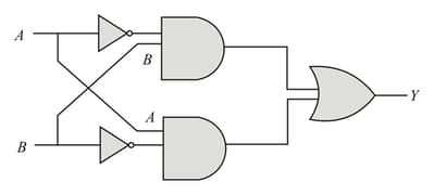
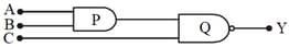
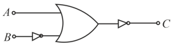
The truth table for the following logic circuit is
Question Image

44.83% studentsanswered this correctly

Important Questions on Electronic Devices

MEDIUM
Select the output Y of the combination of gates shown in figure for inputs A=1,B=0;A=1,B=1 and A=0,B=0 respectively.
Question Image
EASY

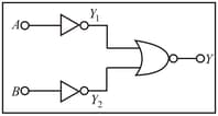
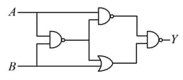
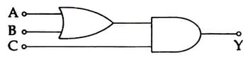
Which logic gate is represented by the following combination of logic gates?

Question Image

MEDIUM

According to the laws of Boolean algebra, the expression A+AB is equal to:

MEDIUM
In the combination of the following gates the output Y can be written in terms of inputs A and B as

Question Image
EASY

Each of the two inputs A and B can assume values either 0 or 1. Then which of the following will be equal to A¯·B¯?

EASY

The input values A and B of the Boolean expression A+B¯A·B¯=1 are respectively:


EASY
What is the output Y in the following circuit, when, all the three inputs A,B,C are first 0 and then, 1?

Question Image
EASY
If A=1 and B=0, then in terms of Boolean algebra, A+B=
MEDIUM
What will be the input of A and B for the Boolean expression A+B¯·A·B¯=1?
MEDIUM
To get output '1' at R, for the given logic gate circuit the input values must be:

Question Image
MEDIUM

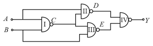
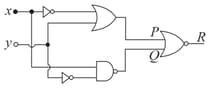
Write the truth table for the given circuit:

Question Image

EASY
The output of an AND gate is connected to the input of a NOT gate. Draw the logic circuit of this combination of gates and write the truth table.
EASY

Question Image

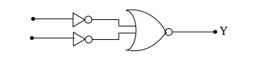
The logic circuit shown above is equivalent to :

EASY
To get output 1 for the following circuit, the correct choice for the input is:
Question Image
EASY
Three variable Boolean expression PQ+PQR+ P ¯ Q+P Q ¯ R can be written as