
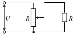
The voltage across a load is controlled by using the circuit diagram shown in the figure. The resistance of the load and of the potentiometer is . The load is connected to the middle of the potentiometer. The input voltage is constant and equal to . Determine the change in the voltage across the load if its resistance is doubled.
Important Questions on Electricity and Magnetism
Given two different ammeters in which the deflections of the pointers are proportional to current, and the scales are uniform. The first ammeter is connected to a resistor of resistance and the second to a resistor of unknown resistance . At first the ammeters are connected in series between points and (as shown in Fig.).
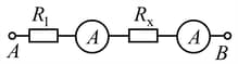
In this case, the readings of the ammeters are and . Then the ammeters are connected in parallel between and
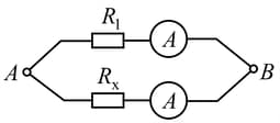
(as shown in Fig,) and indicate and . Determine the unknown resistance of the second resistor.
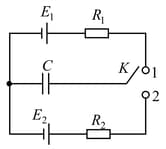
The key in circuit diagram shown in Fig. can be either in position or
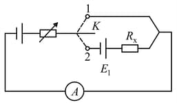
The circuit includes two d.c. sources, two resistors, and an ammeter. The emf of one source is and of the other is unknown. The internal resistance of the sources should be taken as zero. The resistance of the resistors is also unknown. One of the resistors has a varying resistance chosen in such a way that the current through the ammeter is the same for both positions of the key. The current is measured and is found to be equal to .
Determine the resistance denoted by in the diagram.
Can a current passing through a resistor be increased by short-circuiting one of the current sources, say, the one of emf
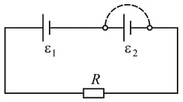
as shown in Fig.? The parameters of the elements of the circuit should be assumed to be specified.
A concealed circuit (black box) consisting of resistors has four terminals. If a voltage is applied between clamps
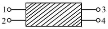
and when clamps and are disconnected, the power liberated is , and when the clamps and are connected, the power liberated is . If the same source is connected to the clamps and , the power liberated in the circuit when the clamps and are disconnected is .
Determine the power consumed in the circuit when the clamps and are connected, and the same voltage is applied between the clamps and .
Determine the current through the battery in the circuit shown in Figure.
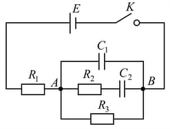
(1) immediately after the key is closed and
(2) in a long time interval, assuming that
The key (Fig.) is connected in turn to each of the contacts over short identical time intervals so that the change in the charge on the capacitor over each connection is small. What will be the final charge on the capacitor?
A circuit consists of a current source of emf and internal resistance , capacitors of capacitance and , and resistors of resistance and .
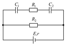
Determine the voltages and across each capacitor.


