
This circuit shows a potential divider. The battery has negligible internal resistance and the voltmeter has infinite resistance.

(a) State and explain how the reading on the voltmeter will change when the resistance of the variable resistor is increased.
Important Questions on Practical Circuits
This circuit shows a potential divider. The battery has negligible internal resistance and the voltmeter has infinite resistance.

Resistor has a resistance of . Calculate the value of the variable resistor when the reading on the voltmeter is .
This circuit shows a potential divider. The battery has negligible internal resistance and the voltmeter has infinite resistance.
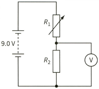
The voltmeter is now replaced with one of resistance . Calculate the reading on this voltmeter.
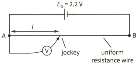
This is a potentiometer circuit.

(a) (i) Sketch a graph of reading on the voltmeter against length, , as the jockey is moved from point A to point B.
This is a potentiometer circuit.

(a) (ii) State the readings on the voltmeter when the jockey is connected to A and when it is connected to B. (You may assume that the driver cell has negligible internal resistance.)
This is a potentiometer circuit.

Draw a circuit diagram to show how the potentiometer could be used to compare the e.m.f.s of two batteries.
This is a potentiometer circuit.
When a pair of resistors are connected in series with a battery, there is a current of current through the battery. When the same two resistors are connected in parallel and then connected across the battery, there is a current of through it. Calculate the e.m.f. and the internal resistance of the battery.
A potentiometer, which consists of a driving cell connected to a resistance wire of length , is used to compare the resistances of two resistors. Draw a diagram to show the circuits that are used to compare the two resistances.
A potentiometer, which consists of a driving cell connected to a resistance wire of length , is used to compare the resistances of two resistors. When resistor alone is tested the length of resistance wire for balance is . There is an uncertainty in measuring the beginning of the resistance wire of , and in establishing the balance point of a further . Determine the uncertainty in the balance length. When and are tested in series the balance length is . There are similar uncertainties in measuring this balance length.


