
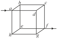
Twelve wires, each having equal resistance are joined to form a cube as shown in figure. Find the equivalent resistance between the diagonally opposite points and
Important Points to Remember in Chapter -1 - Electric Current in Conductors from H C Verma CONCEPTS OF PHYSICS [VOLUME 2] Solutions
1. Electric Current:
(i) Instantaneous current: The rate at which charge flows through a given area of cross-section.
(a) , where is instantaneous charge, and is time.
(b) Current is a scalar quantity.
(c) S.I. unit: or .
(ii) If particles each having a charge passing through a given area in time , then .
(iii) Average current in a given time interval: .
(iv) Amount of charge flowing in a given time interval is
Area under curve.
2. Drift Velocity:
It is the average velocity attained by charged particles, such as electrons, in a material when an electric field is developed in the material.
3. Mobility :
The increase in drift velocity per unit increase in the applied electric field strength.
(i)
(ii) S.I unit: .
4. Relation Between Mobility and Drift Velocity :
. For electrons, and electric field are in opposite directions.
5. Relation Between Electric Current and Drift Velocity :
(i) , where is the electron density, is the charge of an electron and is the area of cross-section.
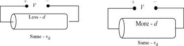
(ii) When a steady current flow through a conductor of non-uniform cross-section, a drift velocity varies inversely with the area of the cross-section, i.e., ;
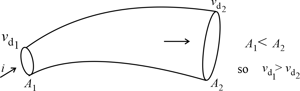
(iii) If the diameter of a conductor is doubled, the drift velocity of electrons inside it will not change.
6. Current Density :
It is defined as the current flowing per unit area of cross-section. Here, the area of cross-section is normal to the direction of charge flow (or current passes) through that point.
(i) Current density at point is given by
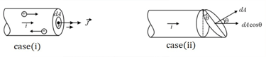
(ii) If the cross-sectional area is not normal to the current, but makes an angle with the direction of current, then
⇒ ⇒
(iii) If the current density is uniform for a normal cross-section , then .
(iv) Current density is a vector quantity.
(v) Its direction is same as that of .
(vi) S.I. unit: .
(vii) Dimensional formula: .
(viii) In case of uniform flow of charge through a cross-section normal to it as
⇒
7. Ohm’s Law:
The current flowing through a conductor is directly proportional to the potential difference applied between the ends of the conductor provided the temperature and physical conditions remains the same,
8. Ohmic Materials:
The materials which obey Ohm’s law are called Ohmic devices or linear devices.
E.g., metals.
9. Non-Ohmic Materials:
The materials which do not obey Ohm’s law are called non-Ohmic devices or non-linear devices.
E.g., semiconductor devices.
10. Vector Form of Ohm’s Law:
, where is the conductivity of the material, electric field.
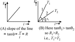
11. Graph between and for a metallic conductor is a straight line as shown in the figure. At different temperatures, curves are different.
12. Relaxation Time :
It is the time interval between two successive collisions of electrons in a conductor.
13. Relation between Drift Velocity and Relaxation Time of Electron:
, where is the relaxation time.
14. Electric Resistance:
The property of the conductor due to which it opposes the flow of electrons (current).
15. Resistance of a Conductor:
The resistance is of a conductor is directly proportional to its length and inversely proportional to its area of cross-section .
, where is the resistivity.
(i) S.I. unit of resistance is .
(ii) If the length of the wire is increased without change in the area of cross-section, then .
(iii) If the wire is stretched without a change in its volume, then .
(iv) Percentage change in resistance:
(a) If the percentage change in the length is , then the percentage change in the resistance is
(b) If the percentage change in the length is , then the percentage change in the resistance is , where .
(v) For a given material, resistivity and density are constants. So,
or
(vi) Hollow cylindrical conductor:
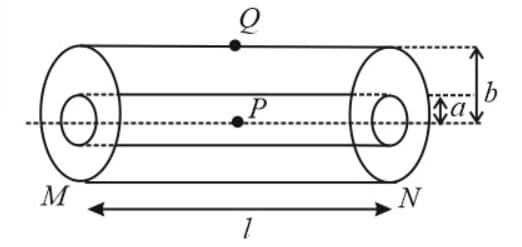
(a) Resistance between ends of the cylinder: .
(b) Resistance between axis and surface of the cylinder: .
(vii) Prism shaped network of resistors:
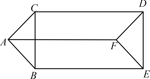
(a) and (b) .
16. Temperature Dependence of Resistance:
(i) Let is the resistance at temperature and is the resistance at temperature . Then, the temperature coefficient of resistance is .
(ii) Let is the resistance at temperature and is the resistance at temperature . Then, the temperature coefficient of resistance is .
(iii) S.I. unit:.
(iv) Temperature coefficient of resistance in the series combination of resistors:
Let and are resistances of two resistors at and their temperature coefficients are and , respectively. The effective temperature coefficient of resistance is .
(v) If the above resistances are connected in parallel, then the effective temperature coefficient is
17. Electrical Resistivity:
Resistivity is numerically equal to the resistance of a substance per unit length having a unit area of cross-section.
(i) S.I. unit: .
(ii) Dimensional formula: .
(iii) Resistivity of metals increases with an increase in temperature and decrease for semiconductors.
(iv) Resistivity is the intrinsic property of the substance. It is independent of the shape and size of the body.
(v) Resistivity increases with impurity and mechanical stress.
(vi) Magnetic field increases the resistivity of all metals except iron, cobalt, and nickel.
(vii) Resistivity in terms of relaxation time: .
(viii) Temperature coefficient of resistivity: .
(ix) is positive for metals and negative for semiconductors.
18. Electrical Conductivity :
The reciprocal of resistivity is called conductivity.
(i)
(ii) S.I. unit: .
(iii) Dimensional formula: .
19. Fuse Wire:
The current in the fuse wire is related to the radius as .
20. Carbon Resistors Colour Coding:
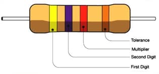
The carbon resistance has normally four coloured rings or bands say and as shown in the following figure.
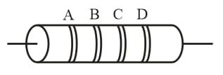
Colour bands and indicate the first two significant figures of resistance in Ohm.
and indicates the decimal multiplier, i.e., the number of zeros that follows the two significant figures and .
and indicates the tolerance in percent about the indicated value or in other words it represents the percentage accuracy of the indicated value.
The tolerance in the case of gold is and in silver is . If only three bands are marked on carbon resistance, then it indicates a tolerance of .
| Letters as an aid to memory | Colour |
Figure
|
Multiplier
|
| B |
Black |
||
|
Brown |
|||
|
Red |
|||
|
Orange |
|||
|
Yellow |
|||
|
Green |
|||
|
Blue |
|||
|
Violet |
|||
|
Grey |
|||
|
White |
The technique to remember the order: BB Roy of Great Britain had a Very Good Wife.
21. Grouping of Resistances:
(i) Series combination of resistors:
(a) Same current flows through each resistance, but potential difference distributes in the ratio of resistance, i.e., ,
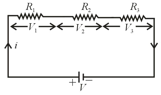
(b)
(c) Equivalent resistance is greater than the highest value of individual resistances.
(d) If identical resistances are connected in series and potential difference across each resistance is .
(ii) Parallel combination of resistors:
(a) Same potential difference appeared across each resistance, but current distributes in the reverse ratio of their resistance, i.e., .
(b) Equivalent resistance is given by,
or or
(c) Equivalent resistance is smaller than the minimum value of resistance in the combination.
(d) If two resistances are in parallel, then
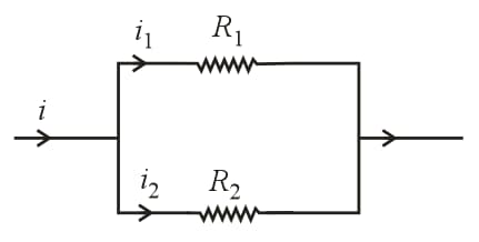
(e) Current through any resistance: , where required current (branch current), main current.
(f) and .
(g) If identical resistances are connected in parallel, then and current through each resistance .
22. Electric Power:
(i) The rate at which electrical energy is dissipated into other forms of energy is called electrical power, i.e., .
(ii) S.I. unit: .
Bigger units are and , .
(iii) Rated values: On electrical appliances (bulbs, heater, geyser, etc.). Wattage, voltage, etc. are printed called rated values, e.g., If suppose we have a bulb of , then rated power while rated voltage .
(iv) Resistance of electrical appliance:
If variation of resistance with temperature is neglected, the resistance of any electrical appliance can be calculated by rated power and rated voltage, i.e., by using .
(v) Power consumed (illumination):
An electrical appliance (bulb, heater, etc.) consume rated power only if the applied voltage is equal to rated voltage , i.e.,
(a) If , then .
(b) If , then . Also, we have .
(c) So, .
(vi) Long distance power transmission:
When power is transmitted through a power line of resistance , power-loss will be ,
(a) If the power is transmitted at voltage , then , i.e., .
So, power loss .
(b) For a given power and line, and are constant, so power loss .
(c) If power is transmitted at high voltage, the power loss will be small and vice-versa. This is why long-distance power transmission is carried out at high voltage.
23. Electricity Consumption:
(i) The price of electricity consumed is calculated on the basis of electrical energy and not on the basis of electrical power.
(ii) The unit for energy is very small, hence a big practical unit is considered known as kilowatt-hour or board of trade unit () or simple unit.
(iii) or is the quantity of electrical energy which dissipates in in an electrical circuit when the electrical power in the circuit is , thus .
(iv) Important formula to calculate the number of consumed units is
24. Combination of Bulbs:
(i) Series combination:
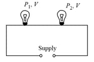
(a) Total power consumed
(b) If bulbs are identical, then .
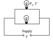
(c) , i.e., in series combination bulb of lesser wattage will give more bright light and appeared across it will be more.
(ii) Parallel combination:
(a) Total power consumed
(b) If identical bulbs are in parallel, then .
(c) , i.e., in parallel combination, bulb of greater wattage will give more bright light and more current will pass through it.
25. Cell:
The device which converts chemical energy into electrical energy is known as an electric cell. The cell is a source of constant emf, but not constant current.
(i) Emf of cell :
The potential difference across the terminals of a cell when it is not supplying any current is called its emf.
(ii) Potential difference :
The voltage across the terminals of a cell when it is supplying current to external resistance is called potential difference or terminal voltage. Potential difference is equal to the product of current and resistance (external) of that given part, i.e., .
(iii) Internal resistance In the case of a cell, the opposition of electrolyte to the flow of current through it is called internal resistance of the cell. The internal resistance of a cell depends on the distance between electrodes , area of electrodes and nature, concentration and temperature of electrolyte .
(iv) A cell is said to be ideal if it has zero internal resistance.
26. Cell in Various Positions:
(i) Closed circuit:
Cell supplies a constant current in the circuit.
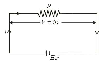
(a) Current given by the cell, .
(b) Potential difference across the resistance, .
(c) Potential drop inside the cell .
(d) Equation of emf of cell , .
(e) Internal resistance of the cell, .
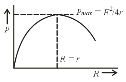
(f) Power dissipated in external resistance (load),
(g) Power delivered will be maximum when . So, .
This statement in generalized form is called the maximum power transfer theorem.
(h) When the cell is being charged, i.e., the current is given to the cell, then
and
ii) Open circuit:
When no current is taken from the cell it is said to be in an open circuit.
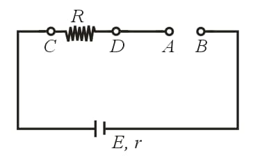
(a) Current through the circuit: .
(b) Potential difference between and : .
(c) Potential difference between and : .
iii) Short circuit:
If two terminals of the cell are joined together by a thick conducting wire, then the cell is said to be shorted.
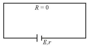
(a) Maximum current (called short circuit current) flows momentarily, .
(b) Potential difference, .
27. Combination of Cells:
A group of cells is called a battery.
In the series grouping of cells, their EMFs are additive or subtractive while their internal resistances are always additive. If dissimilar plates of cells are connected, their EMFs are added to each other while if their similar plates are connected their EMFs are subtractive.
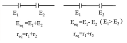
(i) Series grouping: In series grouping, anode of one cell is connected to the cathode of another cell, and so on. If identical cells are connected in series, then
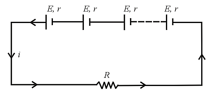
(a) Equivalent emf of the combination: .
(b) Equivalent internal resistance: .
(c) Main current Current from each cell.
(d) Potential difference across an external resistance: .
(e) Potential difference across each cell: .
(f) Power dissipated in the external circuit.
(g) Condition for maximum power and .
(h) This type of combination is used when .
(ii) Parallel grouping: In parallel grouping, all anodes are connected at one point and all cathodes are connected at another point. If identical cells are connected in parallel, then
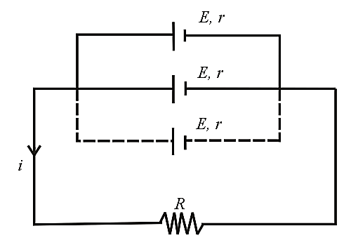
(a) Equivalent emf: .
(b) Equivalent internal resistance: .
(c) Main current: .
(d) The potential difference across external resistance across each cell .
(e) Current from each cell: .
(f) Power dissipated in the circuit: .
(g) Condition for maximum power is and .
(h) This type of combination is used when .
(iii) Mixed grouping: If identical cells are connected in a row and such rows are connected in parallel as shown, then
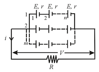
(a) Equivalent emf of the combination: .
(b) Equivalent internal resistance of the combination: .
(c) Main current flowing through the load: .
(d) Potential difference across load:.
(e) Potential difference across each cell: .
(f) Current from each cell: .
(g) Condition for maximum power is and .
(h) Total number of cells .
28. Kirchhoff’s Laws:
(i) Kirchhoff’s first law: This law is also known as junction rule or current law (). According to it, the algebraic sum of currents meeting at a junction is zero, i.e., ,
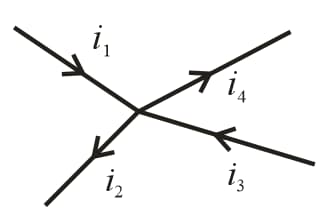
(a) In a circuit, at any junction, the sum of the currents entering the junction must equals the sum of the currents leaving the junction, .
(b) This law is simply a statement of conservation of charge.
(ii) Kirchhoff’s second law: This law is also known as loop rule or voltage law (KVL) and according to it, the algebraic sum of the changes in potential in the complete traversal of a mesh (closed loop) is zero, i.e., .
(a) This law represents conservation of energy.
(b) If there are meshes in a circuit, the number of independent equations in accordance with the loop rule will be .
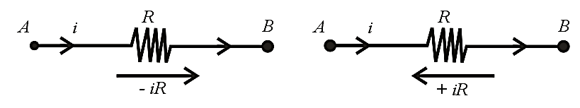
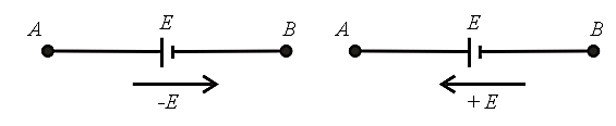
(iii) Sign convention for the application of Kirchhoff’s law:
For the application of Kirchhoff’s laws, the following sign conventions are to be considered.
(a) The change in potential in traversing a resistance in the direction of current is while in the opposite direction ,
(b) The change in potential in traversing an emf source from negative to positive terminal is while in the opposite direction irrespective of the direction of current in the circuit,
29. Terminal Voltage:
(i) Terminal voltage across a battery in an open circuit is , where is the emf of the battery.
(ii) Terminal voltage across a battery during charging is , where is the internal resistance of the cell.
(iii) Terminal voltage across a battery during discharging is .
30. Measuring Instruments in an Electric Circuit:
(i) Galvanometer: It is an instrument used to detect small current passing through it by showing deflection. Galvanometers are of different types, e.g., moving coil galvanometer, moving magnet galvanometer and hot wire galvanometer. In the circuit, usually moving coil galvanometer are used.
(a) Its symbol:
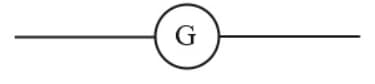
where is the total internal resistance of the galvanometer.
(b) Full-scale deflection current: The current required for full-scale deflection in the galvanometer is called full-scale deflection current and is represented by .
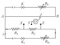
31. Wheatstone's Network:
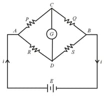
(i) When the current through the galvanometer is zero (null point or balance point), then .
(ii) When .
(iii) If then the products of opposite arms are equal. The potential difference between at null point is zero.
(iv) The null point is not affected by resistance of . It is not affected even if the positions of are interchanged.
32. Metre Bridge:
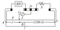
At balance condition: .
33. Potentiometer:
(i) A potentiometer is a linear conductor of uniform cross-section with a steady current set up in it.
(ii) This maintains a uniform potential gradient along the length of the wire.
(iii) Any potential difference which is less than the potential difference maintained across the potentiometer wire can be measured using this. The potentiometer equation is .
(iv) If balancing length is when cells assist each other and it is when they oppose each other as shown then:
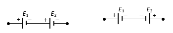
and
⇒ or
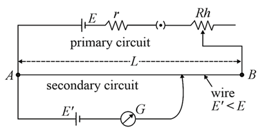
(v) Potential gradient is, .
(vi) Internal resistance of the given cell is calculated using potentiometer by using the formula , where is the balancing length when only cell is connected in the secondary circuit and is the balancing length when cell and external resistor are connected in parallel in the secondary circuit.
(vii) Comparison of resistances: Let the balancing length for resistance (when is connected) is and let balancing length for resistance (when is connected) is .
Then, and .
(viii) Sensitivity of potentiometer: A potentiometer is said to be more sensitive if it measures a small potential difference more accurately.
(a) The sensitivity of the potentiometer is assessed by its potential gradient. The sensitivity is inversely proportional to the potential gradient.
(ix) In order to increase the sensitivity of the potentiometer,
(a) the resistance in the primary circuit will have to be decreased,
(b) the length of the potentiometer wire will have to be increased so that the length may be measured with more accuracy.


