What is logic gate? Draw the schematic symbol for AND, OR, NOT, NAND, NOR gate. Explain its working with the help of its truth table.
Important Questions on Semiconductor Electronics: Materials, Devices and Simple Circuits
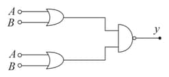
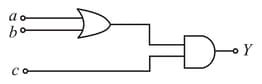
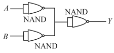
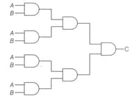
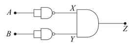
For the combination of logic gates shown in the figure, the equivalent logic gate is
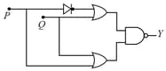
The resultant gate and its Boolean expression for the given circuit is
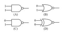
Which of the following gates will have an output of ?
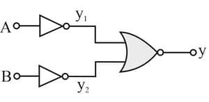
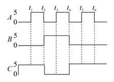
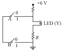
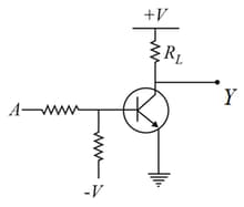
For the given circuit, the input digital signals are applied at the terminals and . What would be the output at the terminal ?
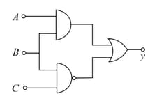
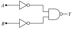
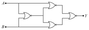
The logic gate equivalent to the given logic circuit is:
The above configuration is equivalent to the
The truth table for the following circuit is
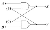
In the circuit shown, inputs and are in states and respectively. What is the only possible stable state of the outputs and
The following figure is the combination of logic gates, The inputs are are The output is Which one of the following choices gives the correct matching ?
Four NOR gates are connected as shown in figure. The truth table for the given figure is :
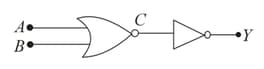
Identify the logic operation carried out by the given circuit:
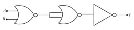
Which logic gate is represented by the following combination of logic gates?