
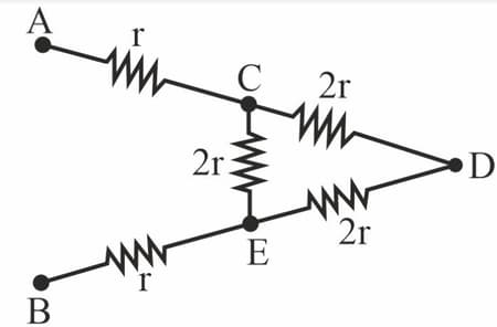
What is the equivalent resistance between points and in the given circuit diagram?
Important Questions on Electricity
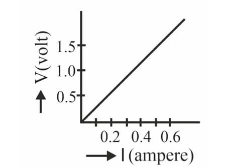
Following graph was plotted between and values, across a wire. Which of the following statement(s) is/are correct regarding this?
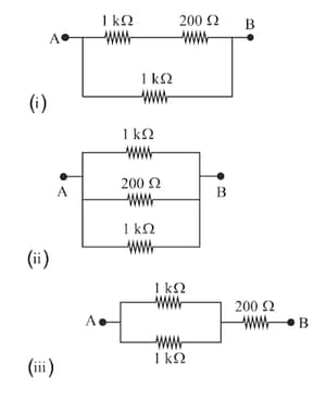
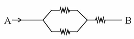
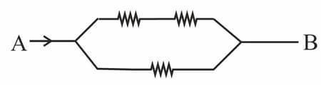
In which of the following network of resistors the equivalent resistance between points and is highest?
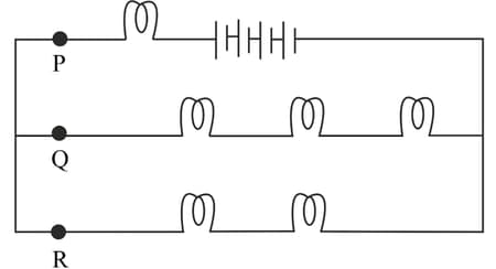
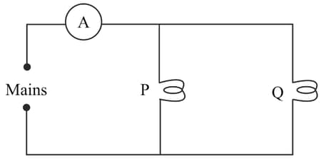
Which of the following statements about the current in given circuit is correct?
(i) If both the bulbs are connected in series then the total power consumption will be .
(ii) If only one bulb is connected then the total power consumption will be
(iii) If the both bulbs are connected in parallel then the total power consumption will be .
Which of the above statement (s) is/are correct regarding the circuit?
How will be the reading in the ammeter A affected if another identical bulb is connected in parallel to ? (The voltage in the mains is maintained at a constant value.)
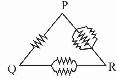
Six equal resistances are connected between points and as shown in the figure. The net resistance will be maximum between :
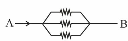
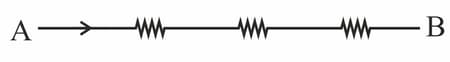
Arrange the order of power dissipated in the given circuits, if the same current enters at point in all the circuits and resistance of each resistor is .
While carrying out an experiment, to find the equivalent resistance of two resistances connected in parallel, a student sets up the circuit as shown. The teacher checks it and tells him that his circuit has one or more of the following ‘faults’.
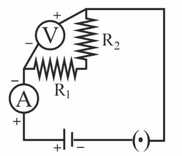
(i) The resistors and have not been correctly connected in parallel.
(ii) The voltmeter has not been correctly connected in the circuit.
(iii) The ammeter and the key have not been correctly connected in the circuit. Out of these three, the actual fault in his circuit is/are :


