
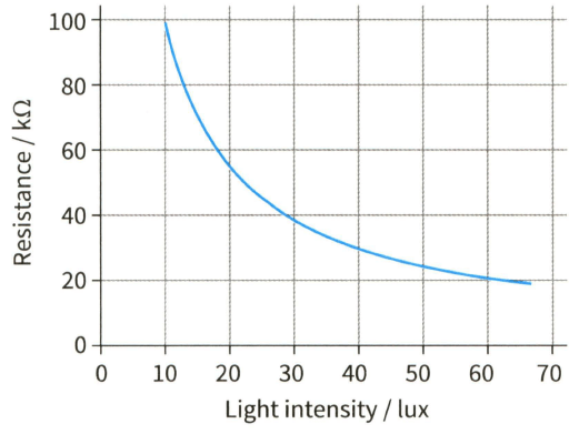
What is the voltage across the resistor in Figure when the light intensity is 10 lux?
Important Questions on Practical Circuits
The circuit shown in Figure produces a decreasing output voltage when the light intensity increases. How can the circuit be altered to produce an increasing output voltage as the light intensity increases?
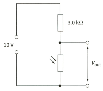
An LDR used as a sensor.
Design a circuit using the thermistor in Figure that uses a cell of and produces an output voltage of at . Explain whether the voltage output of your circuit increases or decreases as the temperature rises.
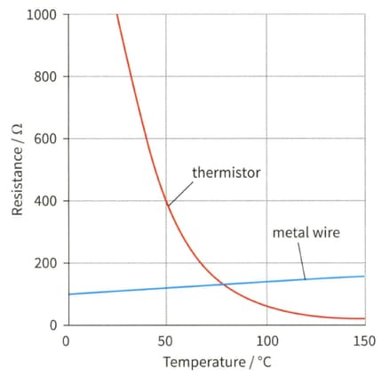
Variation of resistance with temperature.
To make a potentiometer, a driver cell of e.m.f. is connected across a length of resistance wire.
(a) What is the potential difference across each length of the wire? What length of wire has a p.d. of across it?
To make a potentiometer, a driver cell of e.m.f. is connected across a length of resistance wire.
(b) A cell of unknown e.m.f. is connected to the potentiometer and the balance point is found at a distance of from the end of the wire to which the galvanometer is connected. Estimate the value of . Explain why this can only be an estimate.
To make a potentiometer, a driver cell of e.m.f. is connected across a length of resistance wire.
(c) A standard cell of e.m.f. gives a balance length of Use this value to obtain a more accurate value for .
A resistor of resistance and a second resistor of resistance are connected in parallel across a battery of e.m.f. and internal resistance . What is the current in the battery?
(A)
(B)
(C)
(D)


