
Representation of AC Current and Voltage By Rotating Vectors-Phasors
Representation of AC Current and Voltage By Rotating Vectors-Phasors: Overview
This topic consists of various concepts like Phasor Diagram in AC,Phasor Diagram for Pure Resistance Circuit,Phase Difference in Voltage and Current in Pure Resistance, etc.
Important Questions on Representation of AC Current and Voltage By Rotating Vectors-Phasors
Given below are two statements:
Statement-I: In an ac circuit, the current through a capacitor leads the voltage across it.
Statement-II: In a.c. circuits containing pure capacitance only, the phase difference between the current and the voltage is In the light of the above statements, choose the most appropriate answer from the options given below:
Given below are two statements:
Statement-I: In an ac circuit, the current through a capacitor leads the voltage across it.
Statement-II: In a.c. circuits containing pure capacitance only, the phase difference between the current and the voltage is
In the light of the above statements, choose the most appropriate answer from the options given below:
Select the correct phasor diagram of the circuit having only resistance.
Derive an expression for average or mean value of alternating current for half cycle.
An A.C source supply voltage, is applied to a pure resistance circuit containing resistance . Calculate the peak value of current.
If in ac circuit there is no leading or lagging between supplied voltage and current then ac circuit is named as
In a certain circuit, and . Their vector representation is
In a circuit made up of resistance , and inductance , an alternating emf at is connected, then the phase difference between the current and the emf in the circuit is:
resistance and inductance are connected in series with an circuit. The frequency of the source is . Then phase difference in between and will be :-
In a certain circuit and , their vector representation is :-
Two sinusoidal voltages of the same frequency are shown in the diagram. What is the frequency, and the phase relationship between the voltages
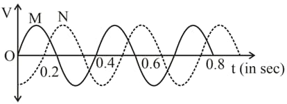
Frequency in Phase lead of over in radians
Assertion: In series AC circuit, voltage leads the current.
Reason: In series AC circuit, current leads the voltage.
In an . circuit, the resistance of is connected in series with an inductance . If the phase angle between voltage and current be , the value of inductive reactance will be:
In series circuit, the phase angle between supply voltage and current is
Voltage and current in an AC circuit are given by and
For the equation where is in seconds, find amplitude and time period.
In a series circuit, the potential drop across and respectively are , and . Then, the source voltage is
A coil of inductive reactance and resistance is connected to a 200 V, 50 Hz AC supply. The time lag between maximum voltage and current is
If the input voltage to the circuit below is given by the output voltage is given by .
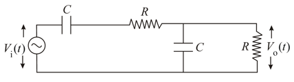
Which one of the following four graphs best depict the variation of vs ?
In an A.C. circuit, the resistance is connected in series with an inductor of self-inductance . If phase angle between voltage and current be , the value of inductive reactance will be equal to.....


