Motional Electromotive Force
Motional Electromotive Force: Overview
This topic covers concepts, such as Motional Emf in a Conductor, Fleming's Right Hand Rule for Induced Current, Derivation of Motional Emf, Motional Emf in a Rotating Conducting Rod and Charge Flown in Changing Magnetic Flux.
Important Questions on Motional Electromotive Force
Two parallel rails of a railways track, insulated from each other and with the ground, are connected to a millivoltmeter. The distance between the rails is one metre. A train is travelling with a velocity of along the track. The reading of the millivotmeter (in ) is (Vertical component of the earth's magnetic induction is,
A copper rod of length is rotated about one end, perpendicular to the magnetic field , with constant angular velocity . The induced emf between the two ends of the rod is,
A solid metal cube of edge length is moving in a positive -direction at a constant speed of . There is a uniform magnetic field of in the positive -direction. The potential difference between the two faces of the cube perpendicular to the -axis, is:
The total charge, induced in a conducting loop, when it is moved in a magnetic field depends on
A conducting wire is moving towards right (with velocity ) in magnetic field . If direction of induced current is as shown in figure then the direction of magnetic field is-

A conducting rod is moving with velocity in a magnetic field . An emf is induced across its ends when-
A long wire is moving with a velocity in a magnetic field of intensity in a direction perpendicular to the field. The emf induced in it will be,
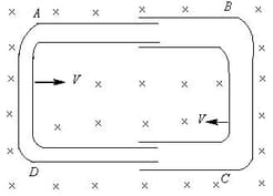
One conducting U-tube can slide inside another as shown in figure, maintaining electrical contacts between the tubes. The magnetic field B is perpendicular to the plane of the figure. If each tube moves towards the other at a constant speed , then the emf induced in the circuit in terms of is the width of each tube, will be