De Morgan’s theorem - Laws and theorems of Boolean Algebra
De Morgan’s theorem - Laws and theorems of Boolean Algebra: Overview
This topic covers concepts, such as, Logic Gates, Truth Table in Logic Gates, Boolean Algebra, De Morgan's Theorem & Proof of De Morgan's Theorem Using Truth Tables etc.
Important Questions on De Morgan’s theorem - Laws and theorems of Boolean Algebra
The same input signal is applied to both the (input) terminals of a given logic gate.
If the output is the(i) same as the (common) input signal
(ii) inverted with respect to the (common) input signal,
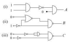
Identify the logic gate/s involved in each case.
What is the use of De Morgan's theorem?
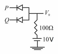
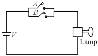
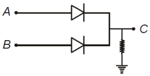
In the given circuit, the input voltages at and could be either or . Use the fact that a diode under forward bias is a short circuit, and under reverse bias is an open circuit. The truth table of the circuit will be that of
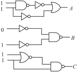
To get output in given circuit, which of the following input will be correct?
Truth table for the given circuit is
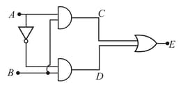
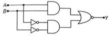
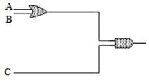
Which logic gate is represented by the following combination of logic gates?
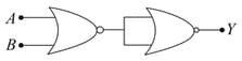
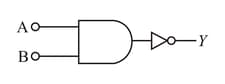
Which logic gate with inputs and performs the same operation as that performed by the following circuit?
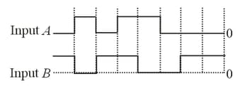
The logic circuit shown below has the input waveforms and as shown in the figure. Pick out the correct output waveform.
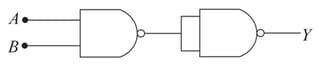
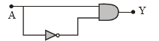
The output of the given logic circuit is,
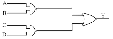
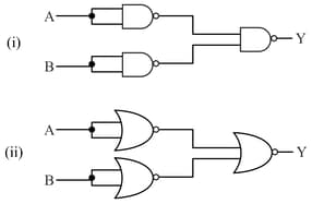
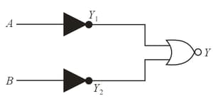
In the following combinations of logic gates, the output of and are respectively
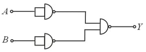
Following diagram performs logic function of
In the following combinations of logic gates, the outputs and are respectively :-
In the following circuit, the output for all possible inputs and is expressed by the truth
table :-
Output of the network shown is:-

Derive the Boolean expression for the output for the gate circuit shown below in the figure.
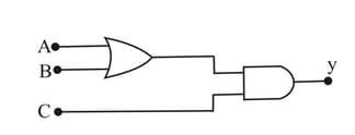
In the circuit represents two inputs and represents the output. Then which logic operation is represented by the circuit,
Given AB. Then the output column in the truth table will be
| A | B | X |
| 0 | 0 | ---- |
| 0 | 1 | ----- |
| 1 | 0 | ----- |
| 1 | 1 | ------- |
To get an output from the circuit shown in the figure, the input must be
What is the Boolean equation for the figure?
In the given circuit, the binary inputs at and are both in one case and both in the next case. The respective outputs at in these two cases will be