
Embibe Experts Solutions for Chapter: Current Electricity, Exercise 4: Exercise-4
Embibe Experts Physics Solutions for Exercise - Embibe Experts Solutions for Chapter: Current Electricity, Exercise 4: Exercise-4
Attempt the free practice questions on Chapter 24: Current Electricity, Exercise 4: Exercise-4 with hints and solutions to strengthen your understanding. Beta Question Bank for Engineering: Physics solutions are prepared by Experienced Embibe Experts.
Questions from Embibe Experts Solutions for Chapter: Current Electricity, Exercise 4: Exercise-4 with Hints & Solutions
For the circuit shown in figure, find
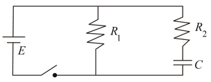
(i) the initial current through each resistor
(ii) steady state current through each resistor
(iii) final energy stored in the capacitor
(iv) time constant of the circuit when switch is closed.
(v) time constant of the circuit when switch is open
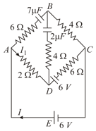
In the network shown in figure, find and the charge on the capacitor after steady state condition is reached.
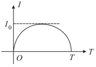
A total charge flows across a resistor during a time interval in such a way that the current time graph for is like the loop of a sin curve in the range . What will be the total heat generated in the resistor.
A rod of length and cross-section area lies along the -axis between and . The material obeys Ohm's law and its resistivity varies along the rod according to . The end of the rod at is at a potential and it is zero at . (i) Find the total resistance of the rod and the current in the wire (ii) Find the electric potential in the rod as a function of .
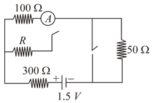
In the circuit shown in figure the reading of ammeter is the same with both switches open as with both closed. Then find the resistance . (ammeter is ideal).
A galvanometer (coil resistance ) is converted into a ammeter using a shunt of and connected as shown in the figure (i). The ammeter reads . The same galvanometer is converted into a voltmeter by connected a resistance of in series. This voltmeter is connected as shown in figure (ii). Its reading is found to be of the full scale reading. Find range of the ammeter and voltmeter.
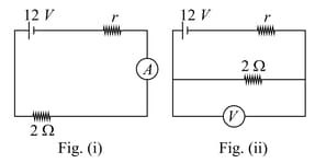
A galvanometer (coil resistance ) is converted into a ammeter using a shunt of and connected as shown in the figure (i). The ammeter reads . The same galvanometer is converted into a voltmeter by connected a resistance of in series. This voltmeter is connected as shown in figure (ii). Its reading is found to be of the full scale reading. Find
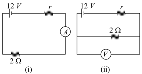
(iii) full scale deflection current of the galvanometer
(ii) Suppose the current density across a cylindrical conductor of radius is maximum at the surface and decreases linearly to zero at the axis so that . Calculate the current.


