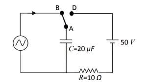
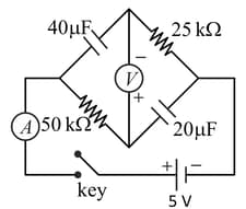
At time , terminal in the circuit shown in the figure is connected to by a key and an alternating current , with and starts flowing in it with the initial direction shown in the figure. At , the key is switched from B to D. Now onwards only A and D are connected. A total charge flows from the battery to charge the capacitor fully. If and the battery is ideal with of , identify the correct statement(s).
Important Questions on Electromagnetic Induction and Alternating Currents
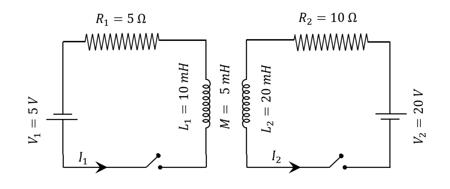
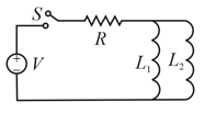
The inductors of two circuits are placed next to each other, as shown in the figure. The values of the self-inductance of the inductors, resistances, mutual-inductance and applied voltages are specified in the given circuit. After both the switches are closed simultaneously, the total work done by the batteries against the induced in the inductors by the time the currents reach their steady-state values is_______.
[Assume the velocity of wire remains constant after key is closed. Given: where is base of the natural logarithm]
and
An ideal voltmeter is configured to read rms value of the potential difference between its terminals. It is connected between points and and then between and . The reading(s) of the voltmeter will be
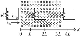
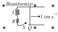
Which of the following schematic plot(s) is(are) correct ? (Ignore gravity)
In the circuit shown below, the key is pressed at time . Which of the following statement(s) is(are) true?
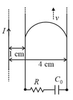
A long straight wire carries a current, ampere. A semi-circular conducting rod is placed beside it on two conducting parallel rails of negligible resistance. Both the rails are parallel to the wire. The wire, the rod and the rails lie in the same horizontal plane, as shown in the figure. Two ends of the semi-circular rod are at distances and from the wire. At time , the rod starts moving on the rails with a speed (see the figure).
A resistor and a capacitor are connected in series between the rails. At time , is uncharged. Which of the following statement(s) is (are) correct? [ SI units. Take ]
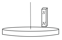
A light disc made of aluminium (a nonmagnetic material) is kept horizontally and is free to rotate about its axis as shown in the figure. A strong magnet is held vertically at a point above the disc away from its axis. On revolving the magnet about the axis of the disc, the disc will (figure is schematic and not drawn to scale)