AC Voltage Applied to a Series LCR Circuit
AC Voltage Applied to a Series LCR Circuit: Overview
This topic covers concepts, such as, Total Impedance in Series L-C-R Circuit, Series LCR Circuit, Impedance Diagram for Series LCR Circuit & Voltage Versus ωt Graph for LCR Series Circuit etc.
Important Questions on AC Voltage Applied to a Series LCR Circuit
An a.c. voltage of , is connected across resistor and inductor in series. What is the impedance of the circuit?
When an inductor and a resistor in series are connected across a , supply a current of flows in the circuit. The current differs in phase from applied voltage by radian. The value of is
What is damped and undamped oscillation?
In circuits, the circuit oscillates if _____ is zero.
In damped oscillation of LCR series circuit charge amplitude is expressed as ( where charge amplitude at )
For small value of resistance damped oscillation of LCR circuit becomes as undamped LC oscillation in respect of angular frequency.
According to voltage vs graph in LCR series circuit, how phasor diagram will be represented.
In LCR series circuit amplitude of voltage across inductor is ( if Peak value of current and inductive reactance)
When resistance is connected in series with an element , the electric current is found to be lagging behind the voltage by angle . When the same resistance is connected in series with element , current leads by . When are connected in series, the current now leads voltage by which is equal to then the value of is (assume same source is used in all cases)
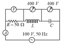
In the series circuit, the voltmeter and ammeter readings are respectively and . Find the value of .
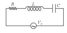
In AC series circuit, the resistance, inductive reactants and capacitive reactants are respectivity. Find the impedance of the circuit.
When is applied across a solenoid, a steady current of flows in it. When is applied across the same solenoid, the current drops to If the frequency of the source is the impedance and inductance of the solenoid are :
Assertion : In a series circuit if and denote voltage across and respectively and is the rms voltage across the source, then
Reason: Kirchoff voltage law is valid only for circuit, but it is not valid for circuit.
What is the impedance of a series RLC circuit with resistance , capacitance and inductance when the frequency of the source is . Round the answer to the nearest integer.
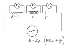
In the figure shown the reading of voltmeters are and Find the peak value of
An AC source of angular frequency is fed across a resistor and a capacitor in series. The current registered is . If now the frequency of source is changed to (but maintaining the same voltage), the current in the circuit is found to be halved. The ratio of reactance to resistance at the original frequency will be,
steady current of flows when an inductor of inductance is connected to ac source of emf . Now capacitor of capacity is connected in series. If the current in the circuit is along the emf, the rms value of the current is
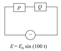
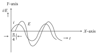
For the ac circuit shown below, phase difference between and current is radian as shown in the graph. If the impedance of the circuit is then the values of and are;
In an circuit, inductive reactance and capacitive reactance was found to be equal. The resistance was found to be The probable impedance of the combination is
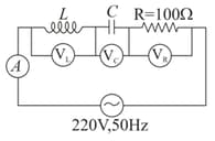
In the given circuit, the reading of voltmeter and are each. The reading of the voltmeter and ammeter are respectively,