
Resonance in Series LCR Circuit
Resonance in Series LCR Circuit: Overview
This topic covers concepts, such as Resonance Frequency, Power Dissipated at Resonance in Series LCR Circuit, Bandwidth of Resonance AC Circuit, Phasor Diagram for Series L-C-R Circuit at Resonance, Half Power Points of Frequency, Resonance, etc.
Important Questions on Resonance in Series LCR Circuit
An circuit is connected to an source. At resonance, the phase difference between the applied voltage and the current flowing in the circuit will be
In a series circuit the resistance was replaced by Which of the following statements is CORRECT?
A circuit consisting of a resistor, inductor and capacitor is connected to an alternating voltage source. At resonance the impedance of the circuit will be
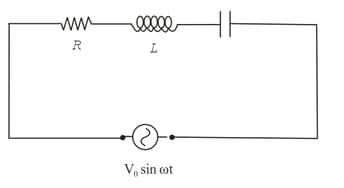
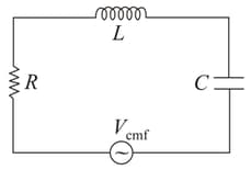
A series LCR circuit has a capacitor in series with a resistance and an inductance The circuit is driven by a voltage
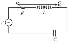
If the circuit is in resonance, the magnitude of the voltage drop across the R-L segment (i.e. drop across the points and ) is
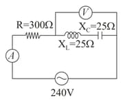
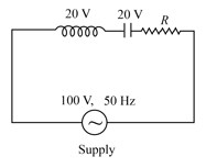
In the following circuit the readings of AC voltmeters and ammeters will be respectively-
Half power point frequencies for which the power in the circuit is half of the ___________________ power in the circuit.
The inductance of the oscillatory circuit of the radio station is and its capacitance is . Taking the effect of resistance negligible, wavelength of the broadcasted waves will be (velocity of light )
In LCR series circuit , then bandwidth of resonance is
The bandwidth of resonance in the A.C. circuit is proportional to inductance.
The inductance of the oscillatory circuit of the radio station is and its capacitance is . Taking the effect of resistance negligible, wavelength of the broadcasted waves will be (velocity of light )
Which one is the expression of resonant frequency in a series resonant circuit?
A parallel L-C circuit comprises of a 5H inductor and capacitor. The resonant frequency of the circuit in is
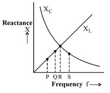
In the given figure, which point shows the resonant state?
In a series resonant circuit, having and as its elements, the resonant current is . The power dissipated in the circuit at resonance is
The given figure represents the phasor diagram of a series circuit connected to an ac source. At the instant t' when the source voltage is given by , the current in the circuit will be :
In the circuit in the figure, and the source of time varying emf has a peak voltage of What should the angular frequency of the source, $\omega$, be to produce the largest current in the resistor?
If value of is changed, then :-
The resonance frequency of the tank circuit of an oscillator when and are connected in parallel is
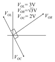
In a series resonant circuit, the AC voltage across resistance , inductor and capacitor are , respectively. The AC voltage applied to the current will be
In series circuit, the resonance condition in terms of capacitive reactance and inductive reactance is


