Kirchhoff's Laws With Capacitors
Kirchhoff's Laws With Capacitors: Overview
This topic covers concepts, such as, Kirchhoff's Law with Capacitors, Kirchhoff's First Law with Capacitors & Kirchhoff's Second Law with Capacitors etc.
Important Questions on Kirchhoff's Laws With Capacitors
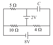
Calculate the potential difference across the capacitor in the circuit (in Volts). (Approximate the answer to the nearest integer)
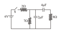
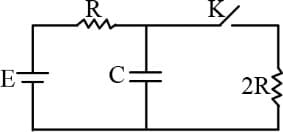
In the circuit shown in figure the switch is initially open and both the capacitors are initially uncharged. If the ratio of current through resistor, just after the switch is closed and a long time after the switch is closed is , find the value of .
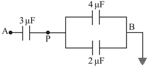
Three capacitors are connected as shown in the figure. Then the charge on capacitor plate is,

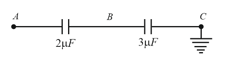
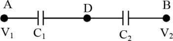
Two capacitors of and are connected in series. The potential at point is and the outer plate of capacitor is earthed. The potential at point is,
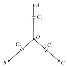
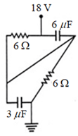
Three uncharged capacitors of capacities and are connected as shown in the figure. and are at potentials and respectively. The potential at is
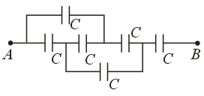
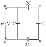
The equivalent capacitance between the points and is
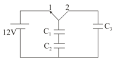
A capacitor and are charged with switch in position Now switch is shifted to position Capacitor is initially uncharged. The ratio of potential difference on and is:
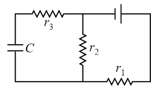
In the given figure, three capacitors and are joined to a battery, with symbols having their usual meanings, the correct conditions will be:-

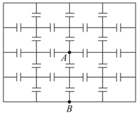
In the figure a potential of is given to point and point is earthed, what is the potential at the point
A charge of is given to point and point is earthed. If each capacitance is , what is the total energy (in ) of the system ?
Three uncharged capacitors of capacitance and are connected as shown in the figure to one another at point . Points and are at potentials and respectively. Then the potential at will be,:

The charge on the capacitor in steady state is in the given diagram. Now, key is closed and steady state charge on is .The ratio of charges will be -

A capacitors of plate area and mass of each plate is charged upto charge . The lower plate is rigidly fixed as shown in figure. Find the value of so that the system remain in equilibrium -

In the given circuit switch is open. The charge on the capacitor is in this steady state is . Now key is closed and steady state charge on is . The ratio is -
In steady state, charge on capacitor is
In the adjacent circuit will be:
In the circuit of following figure, the final voltage drop across the capacitor in steady state is
Two condensers and in a circuit are joined as shown in figure. The potential of point is and that of is . The potential of point will be
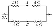
In the circuit shown in the figure, a potential difference of is applied between and . The potential difference between the points and is
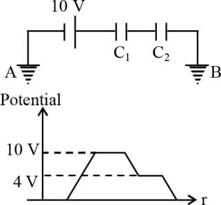
The figure shows two capacitors and connected with battery and terminals and are earthed. The graph shows the variation of potential as one moves from left to right. Then the ratio of is