
RC Circuit with DC Source
RC Circuit with DC Source: Overview
This topic covers concepts such as R-C Circuit, Charging of a Capacitor in R-C Circuit, Charging Current in R-C Circuit, Discharging of a Capacitor in R-C Circuit, Time Constant of R-C Circuit, Variation of Charge with Time in R-C Charging Circuit, etc.
Important Questions on RC Circuit with DC Source
An a.c. voltage, , is applied across a
(i) Series RC circuit in which the capacitative impedance is ‘a’ times the resistance in the circuit.
(ii) Series RL circuit in which the inductive impedance is ‘b’ times the resistance in the circuit.
Calculate the value of the power factor of the circuit in each case.
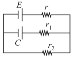
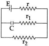
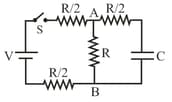
In the given circuit diagram when the current reaches steady state in the circuit, the charge on the capacitor of capacitance will be
and represent the quantities inductance, capacitance and resistance respectively. The combination which has the dimensions of frequency is
Tbe dimension of , where is the resistance and is the capacitance, is the same as that of
In the following circuit the switch is closed at . The charge on the capacitor as a function of time will be given by
A capacitor is charged by battery of potential difference and then connected across a resistor. After one second the potential difference across the plates of capacitor is , then after two seconds from the start, the potential difference across the plates of capacitor is-
If is small then impedance will be mainly decided by:
In the given circuit diagram when the current reaches steady state in the circuit, the charge on the capacitor of capacitance C will be:
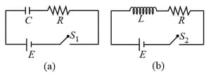
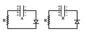
In the given circuits and , switches and are closed at and kept close for a long time. The variation of currents in the two circuits for are shown in the options. (Figures are schematic and not drawn to scale.)
Two identical capacitors and charged to the same potential are connected in two different circuits as shown below at time If the charge on capacitors and at time is and respectively, then (Here is the base of natural logarithm)
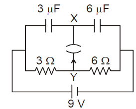
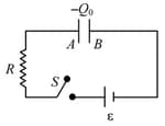
A circuit is connected as shown in the figure with the switch open. When the switch is closed, what is the total amount of charge (in ) that flows from to ?
A charged capacitor is getting discharged in the circuit shown. When the current I was observed to be switch was opened. Determine the amount of heat (in ) that will be liberated in the circuit after is opened.
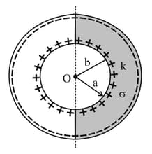
Half portion of a spherical capacitor is filled with a dielectric of dielectric constant and conductivity . The charge given to spherical capacitor is . Due to the conductivity of dielectric charge leaks and the time constant for the discharge circuit is time of . Find the value of .
The figure shows an circuit with a parallel plate capacitor. Before switching on the circuit, plate of the capacitor has a charge while plate has no net charge. If at , the switch is closed then after how much time (in seconds) will the net charge on plate A becomes zero?[Given: , , and ]
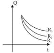
Three identical capacitor are given a charge Q each and they are allowed to discharge through resistor R1, R2 and R3. Their charges as a function of time are shown in graph below. The smallest of the three resistance is:
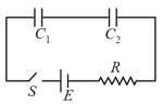
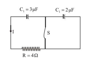
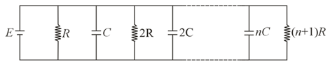
For shown situation, in steady state condition, ratio of charge stored in the first and last capacitor is:-
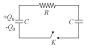
The shown circuit comprises of two identical capacitors of capacitance farads and resistor of resistance . The key is initially open. At time the charge on left capacitor is coulombs and the right capacitor is uncharged as shown. The key is closed at time . Then the magnitude of current in amperes through the resistor at any later time (in ) is
In the circuit shown in figure, the battery is an ideal one with . The capacitor is initially uncharged. Switch is closed at time
The final charge on the capacitor is :
A.DC circuit consisting of two cells of emf and having no internal resistance are connected with two capacitors of capacity and and four resistors and as shown in figure. The ammeter and voltmeter used in the circuit are ideal.
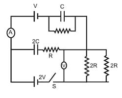
In steady state, the reading of the voltmeter is
For next three question please follow the same
A.DC circuit consisting of two cells of emf and having no internal resistance are connected with two capacitors of capacity and and four resistors and as shown in figure. The ammeter and voltmeter used in the circuit are ideal.

The reading of the ammeter as soon as the switch is closed is


